Typical power supply schemes for electricity consumers
 Power receivers of categories I, II and III with regard to the degree of reliability of the power supply impose different requirements on power sources and circuits.
Category I power receivers must be supplied with electricity from two independent mutually redundant power sources, and interruption of their power supply in the event of a power failure from one power source may be permitted only for the time of automatic power restoration.
To power a dedicated group of Category I receivers, additional power must be provided from a third independent mutually redundant power source. An independent power source for a power receiver or a group of power receivers is called a power source that maintains the voltage within the limits regulated by the PUE for the post-emergency mode when it fails on another or other power sources of these receivers.
Independent power sources include two sections or bus systems of one or two power plants and substations, provided that the following two conditions are met:
1) each section or bus system, in turn, is powered by an independent power source;
2) sections (systems) of buses are not connected to each other or have a connection that is automatically interrupted in case of failure of one section (system) of buses.
Local power plants, power system power plants, special uninterruptible power supply units, storage batteries, etc. Or if power backup is not economically feasible, technological backup is performed.
The power supply of category I power receivers with a particularly complex technological process that requires a long time to restore the operating mode, in the presence of technical and economic studies, is carried out by two independent mutually redundant energy sources, which are subject to additional requirements determined from the characteristics of the technological process.
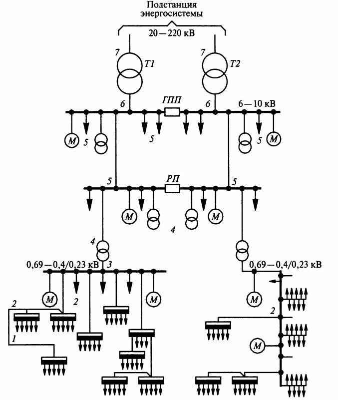
Section of the power supply scheme of an industrial enterprise with the application of characteristic calculation units: T1, T2 — power transformers of the system; GPP — main clamping substation; RP — distribution substation; M — electric motors; 1 — receiver of electricity; 2 — buses of distribution node or main bus; 3 — buses of the distribution device of the transformer substation for voltage up to 1 kV; 4 — transformers of step-down transformer substation; 5 — buses of distribution substation (RR); 6 — GPP tires; 7 — lines supplying the enterprise
Category II power receivers provide electricity from two independent mutually redundant power sources. For Category II power receivers, in the event of a power failure from one power source, power interruptions are permitted for the time required to turn on the backup power by the actions of duty personnel or the mobile operations team. PUE allows powering of receivers for Electricity:
• II category — on one overhead line, including with a cable insert, if the possibility of emergency repair of this line is foreseen for no more than 1 day;
• Category I — one cable line consisting of at least two cables connected to one common device;
• Category II — from one transformer in the presence of a centralized reserve of transformers and the possibility of replacing a damaged transformer within a period of time not longer than 1 day.
For power receivers of category III, the power supply is carried out from a single power source, provided that interruptions in the power supply necessary for the repair or replacement of a damaged element of the power supply system do not exceed 1 day.
Internal power
Radial power circuits for electricity consumers. Radial circuits are those in which electricity from the power plant (enterprise power plant, substation or distribution point) is transmitted directly to the workshop substation without branches along the way to supply other consumers. Such circuits have a lot of disconnecting equipment and power lines. Based on this, we can conclude that the use of radial power schemes should be used only for powering sufficiently powerful consumers.
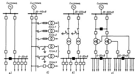
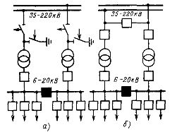
In fig. 1 shows typical schemes of radial power supply of electricity consumers for internal (external) power supply systems of industrial enterprises. The diagram in fig. 1, and is intended for power supply category III users or category II users, where a power outage is allowed for 1-2 days.
The diagram in fig. 1, b is intended for consumers of category II, for which a power outage can be allowed for no more than 1-2 hours. The diagram in fig. 1, c is intended to supply consumers of category I, but is also used to supply consumers of category II, which are of national economic importance on a national scale, and interruption of the power supply, which leads to a shortage of products (for example, release of bearings).
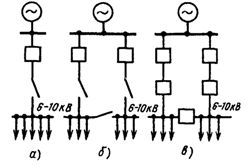
Rice. 1. Typical radial power circuits in the internal and external power supply system of an industrial plant
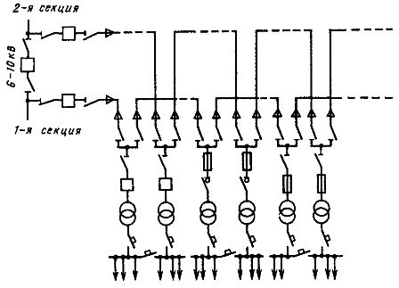
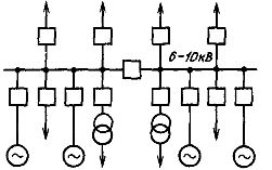
Main power supply circuits for electricity consumers used in the internal power supply system of enterprises when there are many consumers and radial power schemes are clearly recommended. Typically, trunk circuits provide the connection of five to six substations with a total user capacity of not more than 5000-6000 kVA.
In fig. 2 shows a typical power supply circuit. This scheme is characterized by reduced power supply reliability, but it makes it possible to reduce the number of voltage disconnection devices and to more successfully organize power users in a group of five to six substations.
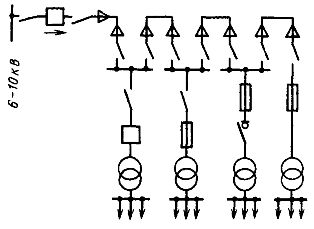
Rice. 2. A typical main power circuit in the internal power supply system of an industrial plant
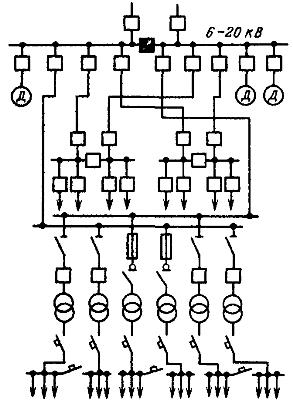
Rice. 3.A typical dual-line power supply circuit in the internal power supply system of an industrial plant
When it is necessary to preserve the advantages of highway circuits and ensure high reliability of the power supply, use a system of double transit (through) highways (Fig. 3). In this scheme, in case of failure of any high voltage supply line, power is provided reliably through the second line by automatic switching of consumers to the low voltage section of the transformer which remains in operation. This switching occurs with a time of 0.1-0.2 s, which practically does not affect the power supply of users.
Mixed power schemes for electricity consumers. In the practice of design and operation of power supply systems for industrial enterprises, it is rare to find schemes built only on the radial or only on the trunk principle. Usually, large and responsible users or receivers are fed radially.
Medium and small consumers are grouped and their food is done according to the basic principle. This solution allows you to create an internal power supply scheme with the best technical and economic indicators. In fig. 4 shows such a mixed power supply scheme.
Rice. 4. Typical scheme of mixed power supply (radial-main) in the internal power supply system of an industrial enterprise
External power supply
It is powered by the power grid without its own power plants. In fig. 5 shows the power supply schemes of industrial plants that are powered only by electric power systems. In fig. 5a shows a radial feed diagram.Here, the voltage of the external supply network coincides with the highest voltage of the network of the territory inside the enterprise (internal power system), so no transformation is required for the enterprise as a whole. Such power schemes are typical for the power supply mainly at voltages of 6, 10 and 20 kV.
In fig. 5, b shows a scheme of the so-called deep block input 20-110 kV and less often 220 kV, when the voltage from the power system without transformation is introduced according to the scheme of a double transit (through) highway to the internal territory of the enterprise. In this scheme, at a voltage of 35 kV, step-down transformers are installed directly in the workshop buildings and they have a lower voltage of 0.69 — 0.4 kV.
However, at power system voltages of 110 — 220 kV, direct conversion from 0.69 — 0.4 kV for commercial networks is usually impractical due to the relatively low total power of consumers in an individual shop. In such cases, intermediate conversion to a voltage of 10 — 20 kV may be recommended at several intermediate step-down substations, each of which must supply its own group of workshops.
In the case of large furnaces or special high-power conversion plants, it may be advisable to convert the 110 or 220 kV voltage directly to the process voltage (usually other than 0.69 or 0.4 kV) by installing special step-down transformers to this directly in the workshop buildings.
In fig.5, c shows a possible power supply scheme for an industrial enterprise with the presence of a transformation carried out at the point of transition from an external to an internal power supply scheme, which is typical for enterprises with significant power and a large territory. In fig. 5, d, a diagram is given under the condition of transformation into two voltages, which is characteristic of powerful units (workshops) of enterprises located at a significant distance from each other.
Power supply from the power system if the industrial enterprise has its own power plant.
Rice. 5. Typical power schemes when powering industrial enterprises only from the power system
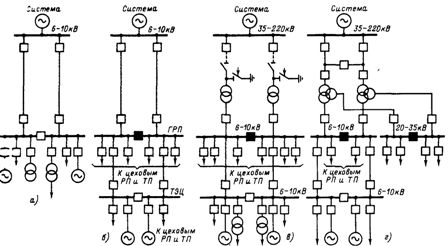
Rice. 6. Typical power supply schemes when supplying industrial enterprises from the power system and their own power plant
In fig. 6 shows typical power supply schemes of industrial enterprises, if the enterprise has its own power plant. In fig. 6 and a diagram is given for the case when the location of the power plant coincides with the center of the electrical loads of the enterprise and the supply of the enterprise from the power system is carried out at generator voltage.
In fig. 6, b shows a diagram for the case when the power plant is located at a distance from the center of its electrical loads, but the power supply from the system is obtained at the voltage of the generator. In fig. 6, c shows a diagram for the case when the power supply from the system is carried out at increased voltage and the distribution of electricity on the territory of the enterprise occurs at the voltage of the generator. The power plant of the plant is located outside the center of electrical loads.
In fig.6, d shows a circuit whose conditions are similar to the circuit shown in FIG. 6, c, but the transformation is carried out at two voltages. In the diagrams of Figs. 5, b, d and fig. 6, d for power supply from the system at a voltage of 35 — 220 kV, the options shown in fig. 7. The diagram in fig. 7, a (without switches on the high voltage side) is recommended as cheaper in design and no less reliable in operation than the circuit in fig. 7, b.
Rice. 7. Schemes for connecting the transformers of the GPP to the power supply network of 35 — 220 kV of the power system
The application of the scheme of fig. 7, but it is possible only for those cases when the operation of turning on and off the transformers is not carried out every day, since they observe the economically feasible mode of their work. If the transformers are turned off and on every day, choose the scheme shown in fig. 7, b.
It is powered only by its own power plant. In fig. 8 shows a diagram of the supply of electricity consumers from their own power plant, which is typical for enterprises remote from the power system networks; however, with the development of electrification, the number of such power schemes will continue to decrease.
Rice. 8. Typical power supply scheme when powering an industrial enterprise only from its own power plant
When powering workshops that have vacuum electric furnaces of all types, it should be borne in mind that the interruption of the power supply to the vacuum pumps leads to an accident and the rejection of expensive products. These ovens should be classified as Category I power receivers.