Automatic switch-on of back-up power supply (ATS) in distribution networks
 Automatic Transfer Switch (ATS) designed to switch users from a failed power source to a serviceable, backup. In rural power supply systems, ATS devices are used on two-transformer 35-110/10 kV substations (local ATS) and on 10 kV bidirectional power lines operating in open mode (mains ATS).
In connection with the appearance of consumers of the first category in terms of power supply reliability (livestock complexes), they began to introduce ATS devices at TP-10 / 0.38 kV, on 0.38 kV lines and in backup diesel power plants.
The following basic requirements are imposed on ATS schemes:
• ATS must be provided in the event of an unexpected power failure for any reason and in the presence of voltage in the backup power source;
• ATS must be performed with the shortest possible working time;
• ATS must be one-time;
• The ATS must provide a quick shutdown of the backup source when a stable short circuit is turned on, for this it is recommended to speed up the protection after the ATS (in the same way as it is done after the AR);
• the ATS scheme must provide for monitoring of the serviceability of the circuit for switching on the backup equipment.
To start the automatic transfer switch when the main source voltage disappears, an undervoltage relay is used... In some cases, the role of the trigger is performed by a time relay with a return armature (in normal mode, the time relay is constantly energized and the anchor is pulled).
The receiving setting of these relays is usually selected, if no specific data is available, from the condition

The response time of the starting element of the ATS device (tav.AVR) is selected according to the following conditions:

where ts.z is the longest response time of the specified protections;
Δt is the degree of selectivity assumed equal to 0.6 s when using a time relay with a scale of up to 9 s and equal to 1.5 ... 2 s with a scale of up to 20 s;
• by coordinating the action of the automatic transfer switch with other automation devices (for example, the automatic reclosing of the line through which energy is supplied from the main power source)

where ts.z.l — the longest time of operation of the protection of the line (element of the power supply system) transmitting energy to consumers for which an automatic transfer switch is performed;
t1APV — failed auto-close cycle time of this row;
tzap — time limit taken equal to 2 — 3.5 s.
In rural electrical networks, network ATS, which provide redundancy to consumers connected to bidirectional power lines operating in open (conditionally closed) mode (Fig. 1, a).
Network ATS is a set of devices that includes:
• the ATS device itself, which switches power to the backup source by turning on the ATS point switch (3B, Fig. 1), which is turned off in normal circuit operation;
• devices that provide, if necessary, automatic restructuring of the relay protection before changing the operating mode of the network during automatic transfer switching;
• automatic minimum voltage separation device (1V and 5V shutdown is valid, fig.1, a), which prevents the supply of voltage from the backup source to the damaged source of working power (to the working line, transformer, etc.), as well as to some other devices.
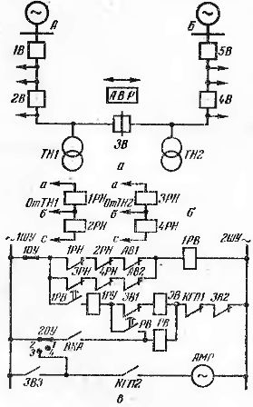
Rice. 1 Scheme of a network automatic switch for rural networks of 10 kV (on a spring-operated circuit breaker): a — explanatory primary circuit of a network of 10 kV; b — voltage circuit diagram of the ATS starting body; c — diagram of automatic transfer switch and control of switch 3 (automatic transfer switch point).
Figure 1, c shows a diagram of a network ATS for spring-operated circuit breakers, the most common in rural 10 kV networks. At the ATS point (Fig. 1, a) a KRUN cell (cabinet) with a 3V switch, equipped with a network ATS and relay protection, is installed.
The action of the starting element of the ATS is provided by voltage transformers TN1 and VT2 (two or one VT on each side), which are sources of operating current for all devices of the ATS point.In this case, the supply of control busbars 1ShU and 2ShU (Fig. 1, c) is carried out either from TN1 or from TN2 with automatic switching to TN of the undamaged line.
When the power fails, for example on the side of substation A, the voltage relays 1PH, 2PH are activated. In the presence of voltage on the side of substation B, the time relay 1RV turns on and after a certain time closes the contact 1RV in the circuit of the electromagnet for turning on the EV of the 3V switch.
If the drive springs are engaged (contact KGP1 is closed), the circuit breaker is closed. If the automatic transfer switch is successful, the motor is engaged via the closed auxiliary contact 3VZ and starts the drive springs. In the event of an unsuccessful ATS (short-circuit inclusion with subsequent disconnection from the protection), the ZVZ contact remains open and the springs are not wound (the duration of the complete winding of the springs is 6 ... 20 s). This guarantees the one-time ATS.
In this case, to prepare the drive for switching on, it is necessary to manually move the device 2OU to position 2-3. In case of faults in the circuits TN1 or TN2, the corresponding breaker AB turns off and its auxiliary contact AB1 or AB2 disables the ATS device to operate to the damaged VT.
If the tav.AVP settings when the voltage disappears from sources A and B are significantly different, then a second relay 2PB is installed (not shown in the diagram), so that the relay 1PB is triggered on the circuit 1PH, 2PH, AB1, and the relay 2PB — on the circuit 3PH, 4RN, AB2.
The operation of the ATS circuit of transformers is checked on the stand (Fig. 2).
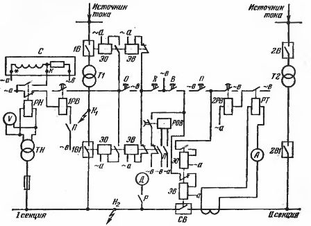
Rice. 2. Schematic of the ATS device (section switch switching) of a two-transformer substation.
The schematic diagram of the automatic transfer switch, shown in figure 2, allows, through a section switch CB, to automatically supply the busbars of section I or II in the event of an emergency shutdown of transformers T1 or T2.
Consider the operation of the circuit when the backup power is connected to the Section I buses.
Section I consumers are normally supplied by transformer T1, and their automatic supply redundancy is achieved by turning on SV.
Automatic back-up power is supplied when the voltage on the section I busbars fails due to:
• disconnection of the power supply or the supply wire on the side of T1;
• short circuit inside the transformer and on the busbars of section I;
• unintentional disconnection of transformer T1.
The ATS circuit operates only when the contacts of switch P. The coil of the ATS device single-turn relay (ROV) is energized and its contact is closed while switch 1B1 is on.
When the voltage on the section I buses disappears, the undervoltage relay closes its break contacts. Through its closed contacts, the time relay 1PB receives power and after some time delay gives an impulse to turn off the transformer T1 (switches 1B and 1B1).
Usually, the time relay acts on an intermediate relay, which with its contacts turns on the working circuits of the switch. After switching off the switches, the DOM coil is turned off, but its contacts return to their initial position with a certain time delay. The return time is slightly longer than the closing time of the CB switch.Therefore, the CB on pulse manages to pass through the ROV contact and turn it on, due to which the busbars of section I receive power from transformer T2. After opening the ROV contact, the pulse circuit to close the switch is interrupted, which ensures the one-time operation of the ATS device.
To exclude false actions of ATS devices when fuses are blown in the VT voltage transformer circuit, two undervoltage relays are installed with series connection of their contacts. In addition, another voltage relay can be connected in series, which is powered from a backup source and allows the ATS device to operate in the event of a voltage failure in the main section for these users only if there is voltage on the backup power spikes.
See also on this topic: How automatic transfer switching devices (ATS) work in electrical networks