Basic connection schemes of current transformers and relays
 When applying protection, various schemes are used to connect current transformers and relay coils, primarily a complete star circuit, an incomplete star circuit and a relay switching circuit for the difference in the currents of two phases (Fig. 1).
In rural electrical networks, the incomplete star scheme is currently most often used. In differential protection of power transformers and generator-transformer blocks, as well as in other protections, a scheme is used to connect current transformers to a delta, a relay to a star.
The choice of a specific connection scheme is determined by a number of factors: the purpose of the defense, types of damage to which the protection must respond, conditions of sensitivity, requirements for ease of implementation and operation, etc.
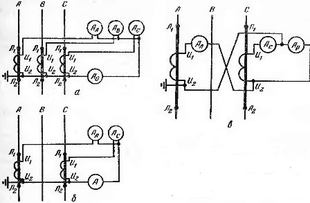
Rice. 1. Schemes for connecting current transformers and relays: a — full star; b — incomplete star; c — inclusion of a relay for the difference in the currents of two phases.
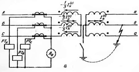
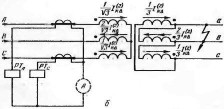
Rice. 2. Distribution of currents in the windings of the power transformer in the event of a short circuit.behind it: a — protective circuit — full star, power transformer — Y / Y -0; b — protective circuit — incomplete star, power transformer — Y / Δ.
Each scheme is characterized by its own value of the coefficient of the scheme, which is understood as a ratio

where Ip is the current flowing in the relay coil; I2.tt — current in the secondary winding of the current transformer.
In circuits where the relay is switched on for phase currents, kcx = 1. For other circuits, kcx may have different values depending on the type of k. Z. So, for a circuit for turning on one relay for the difference in the currents of two phases A and C


The distribution of currents in the primary circuits and the operation of various protection schemes are affected by power transformers with the connection of the windings Y / Δ and Y / Y-0.
Figure (2, a) shows the distribution of the current in the primary circuits with a short circuit of phase B behind the transformer with the connection of the windings Y / Y-0. In this case, at the short-circuit location, the current flows only in the damaged phase, and on the supply side - in all three phases. In phases A and C, the currents are equally directed, equal in value and 2 times smaller than the current in phase B.
In this and another similar case, with a two-phase short circuit. behind the transformer with the winding connection Y / Δ (Fig. 2, b), the incomplete star circuit may have reduced sensitivity, and the relay switching circuit for the difference between the currents of the two phases fails (the current in the relay is 0).
To measure the highest short circuit current. include an additional relay in the return wire of the partial star circuit to increase its sensitivity.
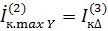
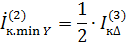
When checking the sensitivity of protections, it is necessary to take into account that the largest current on the side of the star with a two-phase short circuit. on the side of the triangle in relative units is equal to the three-phase short-circuit current. on the side of the triangle:
and the minimum current is equal to half of it:
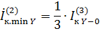
For a transformer with a winding Y / Y-0 (Fig. 2, a)
The current transformer and relay switching scheme determines the load of the current transformer and its faults.
In earthed neutral systems, a single-phase earth fault is a short circuit and can be detected by an increased phase current.
In rural power supply schemes, single-phase short circuits. are observed in networks with a grounded neutral voltage of 0.38 kV, and simple earth faults are observed in networks of 6 ... 10, 20 and 35 kV.