Schemes of input and distribution devices (ASU) of residential buildings
 In modern residential buildings, the inputs of external networks and switching and protection equipment of distribution lines of internal networks are combined in a single integrated input-distribution unit (ASU), which is also the main switchboard.
The input scheme depends on the scheme of external power lines, the number of floors of the building and reliability requirements, the presence of elevators and other energy consumers, the presence of built-in enterprises and institutions, the magnitude of electrical loads. Depending on the listed conditions, the building receives power from one, two, and sometimes more inputs.
Typical bushing diagrams.
In fig. 1 shows typical bushing schemes: single with switch and fuses (Fig. 1, a), single with switch (Fig. 1, b), single with switch and fuses (Fig. 1, c), double with switches and fuses ( Fig. 1, d), double with an automatic switch for electric receivers of the first reliability category (Fig. 1, e).
Currently, in order to increase the reliability of the power supply of fire extinguishing devices and to completely turn off the electrical receivers of the house in the event of a fire, the installation of a special shield connected to the cable seals before the input switches is used. This scheme is used for houses with a height of 16 stories or more and is shown in fig. 1, f.
The inputs shown in Fig. 1, a and b, are used for buildings up to five floors including without elevators and other energy consumers. The input shown in Fig. 1, c, can be used for houses up to and including five floors. This scheme provides redundancy, but with a dead end, the redundant cable does not work normally (cold standby), which is its disadvantage.
In fig. 1, d shows a diagram of a double entrance in a building with a height of 6 to 16 floors inclusive with mutual redundant entrance. For buildings over 16 floors, the diagram in fig. 1e, in which the power supply of elevators, emergency lighting and fire-fighting devices is automatically archived. Cables shown with dashed lines are intended to supply power to neighboring buildings with a main power supply scheme. For dead ends, these cables are not necessary.
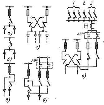
Rice. 1. Diagram of entrances: 1 — smoke fans and valve drives, 2 — emergency lighting on escape routes, 3 — fire alarm circuits.
In some cities, for example, St. Petersburg, a different system for the device of entrances to residential buildings has been preserved with the installation of the so-called. A junction point outside the building on the wall to which the power cables from the substation are fed. Several sets of fuses are installed at the separation point.The switchgear in the house is fed from the split point.
The separation point is operated by the energy organization and serves as the boundary of the operational affiliation of the networks of the energy organization and housing maintenance offices. It should be recognized that such a network system is outdated and in the future should be replaced by the schemes described earlier.
Installation of protective devices
In a radial power scheme (the cable feeds one house), the PUE is allowed not to install protective devices at the entrance. However, their installation is recommended, since the protective device at the input provides protection to the lines coming out of the ASU (the failure of which leads to the interruption of the substation and, therefore, to the emergency service of the power system), and current limiters at the inputs make it possible to use light output line fuses.
When two or more buildings are fed by one line, the installation of protective devices at the entrances is mandatory.
For powering low-rise buildings with branch current up to 20 A, input devices are not used in buildings; the fuses are installed at the beginning of the branch of the support of the air network.
Distribution part of ASU
The distribution portion of the ASU includes supply lines for apartments, energy consumers and emergency lighting, lighting networks for staircases and other common building premises, built-in enterprises and institutions.
All outgoing lines are equipped with protective devices, fuses or circuit breakers.The use of automatic switches should be considered preferable, since they are more reliable than fuses, the fuses of which, after the first melting, are often replaced with home-made uncalibrated inserts.
Automatic switches create additional convenience in operation, performing the functions of switching devices in addition to protection. This is even more important because when fuses are used to save money and reduce the size of the ASU, switching devices are not installed in them, which is a serious drawback of such input distribution devices.
A characteristic feature of the construction of the ASU chain of the house is the separate power supply of the loads of the apartments and the working lighting of the common building premises from one entrance and the energy consumers from the other. The need for such distribution is explained by different electricity tariffs for consumers of electricity and lighting in residential buildings, as well as the impact of frequent starts of elevator motors on the operation of lighting installations, radio stations and televisions. As the calculations show, in most cases the voltage drop when turning on the elevators exceeds the permissible value according to GOST.
In accordance with the above, the grouping of output lines by inputs is usually done as follows.
First input:
1) apartment delivery lines,
2) power lines and group lighting for common building premises (stairs, corridors, lobbies, halls, technical underground floors, ceilings), lighting of entrances to the house, lamp with numbers, etc.,
3) power line for electrical receivers of built-in enterprises and institutions that do not cause voltage fluctuations above permissible limits.
Second entrance:
1) power line for elevators,
2) supply and group lines of emergency lighting (for emergency lighting, voltage fluctuations are not standardized),
3) power lines for fire fighting devices,
4) power lines for electric receivers for economic purposes (cold and hot water supply pumps), if these electric receivers are located in a building,
5) power lines for electricity consumers, built-in enterprises and institutions.
In some cases, when it is advisable according to the conditions of distribution of loads on the entrances, it may be allowed to supply the lighting installations of the tenants from the incoming power, but the possibility of their connection is checked by calculation. This usually leads to an increase in the cross-section of the power cable, especially when the distance from the substation is 150 m or more.
It should be borne in mind that the current loads of each input should not exceed 400 A, and in exceptional cases 600 A, to avoid the need to lay bundles of parallel cables and install heavy devices at the inputs.
The use of power bushings must be coordinated with the scheme of the power plant, in particular with the selection of ATS equipment. As mentioned above, for large extended buildings, the number of entrances can be increased.
Measurements and accounting
Measurement of active electricity consumed by ordinary household consumers is carried out by three-phase meters with direct connection (up to 50 A) or by current transformers, which are installed on the branches to the corresponding sections of the ASU busbars. At the same time, separation of measuring devices for power and lighting installations. Emergency lighting, usually connected to the power supply, is counted by the energy consumer meter. For the ability to change the meter without removing the voltage from the ASU, a disconnect device is installed in front of the ASU meter.
According to the established practice, meters are not installed in the ASU of residential buildings. However, in large buildings, especially in buildings with electric furnaces, control of current loads and voltage values is desirable. At the same time, it is important to have ammeters in all three phases in order to fix the asymmetry of the loads and take measures for its eventual equalization. Measuring instruments (three ammeters with current transformers and one voltmeter with a switch) should be installed at each input.