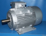
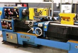
Advantages of using multi-speed motors
 The replacement of conventional single-speed engines with multi-speed ones in many cases significantly improves the technological and operational qualities of machines and metal-cutting machines and reduces the labor intensity of their production.
Multi-speed motors are used:
-
in machine drives and metal-cutting machines, the speed of which is desirable to change depending on the size, hardness and other physical properties of the processed material or depending on technological factors. These include metal cutting and woodworking machines, centrifugal separators, dredges and other mechanisms for various applications;
-
in machines, metal-cutting machines and mechanisms with different operating and idle speeds (sawmills);
-
for starting and stopping without sharp impacts on tables with significant momentum (elevators, hoists). In this case, the work process takes place at the highest speed of rotation, and the start and stop of the mechanism — at low revolutions, often with automatic switching of the number of poles;
-
in machine drives and machine tools with power that varies depending on the time of day, season, etc. (pumps, fans, cargo devices, conveyors, etc.);
- in machine drives with several different purposes each requiring a different speed, for example oil well equipment where the lowest speed is used to pump oil and the highest speed is used to install pipes;
-
in mechanisms whose speed change is determined by the consumed power. An example is flat rolling mills, where initially, with significant metal deformation, rolling is carried out at a low speed, and finishing operations at a high speed.
-
in blocks, where in addition to regulating the speed of rotation of the motor by switching the number of poles, an additional increase in the speed control limit is carried out by changing the frequency of the supply network.
Thanks to the use of multi-speed motors in electric drives of machines and metal-cutting machines, it is possible to:
1) simplifying the design of the machines to the exclusion of gearboxes and power supplies;
2) increasing the performance, productivity and ease of maintenance of metal cutting machines;
3) improving the quality of machine processing by reducing vibrations and reducing inaccuracy in the operation of mechanisms with a large number of gears;
4) increasing the efficiency of the machine by reducing the intermediate links of the kinematic chain;
5) changing the speed in motion without stopping the machine;
6) simplifying the automatic management of the processes of starting, stopping, reversing and stopping;
7) simplification of automatic management of processing modes depending on technological factors.
Starting the motor at a lower rotational speed also has the advantage that the absolute value of the starting current in this case will, as a rule, be less than the starting currents for higher speeds. When switching the coil from a smaller to a larger number of poles, i.e. when the motor speed slows down, regenerative braking of the engine, which shortens the machine's stopping time and is not associated with energy losses, as is the case with reverse braking.
There are wide opportunities for using multi-speed motors in a wide variety of types of universal and special automated metal-cutting machines: turning, turning lathes, drilling, milling, grinding, longitudinal and transverse planing, sharpening, etc.
Multi-speed motors are most widely used in machine tool and woodworking machine drives.

A significant range of speed regulation of universal metal cutting machines requires reducers or gearboxes with a large number of control steps. When the adjustment process is carried out in only one mechanical way, the gearboxes are structurally much more complex and require a more complex control system.
Both factors cause an increase in labor intensity and an increase in the cost of manufacturing gearboxes.Therefore, a compound speed control system is widely used in machine tools, which is a combination of an electric motor, the speeds of which are regulated over a fairly wide range, with a gearbox or relative idler with higher efficiency compared to more complex gearboxes.
It is especially advisable to use multi-speed motors in metal cutting machines, where you can limit yourself to two, three or four different speeds at a machine spindle speed equal to the motor speed. In this case, built-in multi-speed motors are used. The stator of the motor is built into the headstock of the machine, and the spindle is connected by a coupling to the rotor shaft of the motor, or the rotor of the motor is mounted directly on the spindle.
Such a design of the machine turns out to be extremely simple, its kinematic chain is the shortest, and the engine is as close as possible to the working shaft.
If the speed of rotation of the spindle of the metal cutting tool does not correspond to the speed of rotation of the multi-speed motor, the latter is connected to the spindle by means of a belt or gear drive. A similar kinematic diagram is used for operating rooms of lathes, milling machines or small drilling machines. Adding simple search to such a scheme greatly expands the range of machine speed control, extending the machine's kinematic chain only at low rotational speeds.
The use of a multi-speed motor in the electric drive of the machine tool, connected directly to the speed variator, greatly expands the possibility of smooth control of the speed of the machine.Application, for example, a two-speed engine 2p = 8/2 and a mechanical variator with a speed ratio of 4: 1, you can implement to set stepless speed control from 187 to 3000rpm, i.e. get a 16:1 adjustment range.
With a 500/3000rpm two-speed motor and a 6:1 ratio variator, the range of smooth machine speed control is extended to 36:1. achieved by using boost after the variator.
The range of smooth drive speed control can be moved into the area of higher or lower speeds by changing the speed of rotation of the multi-speed motor. If this is not enough, an overdrive or downshift is placed between the engine and the variator, most often a V-belt or belt.
For smooth speed regulation in a relatively small range up to 1:4 with constant shaft torque, an asynchronous motor with sliding clutch.
The efficiency of such a motor is determined by the expression η = 1 — s, where s is the slip equal to the difference between the rotational speeds of the rotor and the output shaft. Therefore, at s = 80%, the efficiency will be only 20%. In this case, all power losses are concentrated in the clutch drum.
By replacing a conventional single-speed motor with a multi-speed one in a sliding clutch drive, it is possible to increase the efficiency and extend the range of speed regulation of this drive.For example, in a two-speed motor with a 2:1 pole change ratio, speed control is performed in steps of 2:1 ratio, and in the interval between these speeds and below them, smooth adjustment is performed by the slip clutch. The overall control range will be 4:1 with a minimum efficiency of 50%.
Due to the fuller use of the regulating properties of the couplings (control range 5: 1), it is possible to extend the control range to 10: 1 at the lowest efficiency (at the lowest speed of rotation of the shaft) η = 20 %.
Application of a three-speed motor with a pole-changing winding 2p = 8/4/2 allows to increase the control range to 8: 1 at the lowest drive efficiency η = 50% and reach the control limit of 20: 1 at efficiency at the lowest speed η=20%.
