Schemes for connecting ammeters through current transformers
 In current measuring circuits, both when the devices are connected directly and when they are connected through instrument current transformers only ammeters are used.
The schemes for connecting ammeters through current transformers are shown in fig. 1.
The current transformer provides a measurement error corresponding to its accuracy class only when it measures the current in a certain range, and the load resistance in the secondary winding must not exceed the specified value. So, the accuracy class of TC-0.5 type current transformers with a load resistance of 1.6 ohms will be 1.0. As the load resistance increases to 3 Ohm, the accuracy class decreases to 3.0, and when a 5 Ohm load is connected to the secondary winding, it becomes equal to 10.0.
The resistances when making up a real circuit can be estimated approximately as follows.
Resistance of connecting wires Rc = ρl / S,
where ρ — resistance of the wire material (for copper wires ρ= 0.0175 μOhm x m, for aluminum wires ρ = 0.028 μOhm x m); l — length of connecting wires, m; C — cross-sectional area of the wires, mm2.
The total resistance of the contact connections Rk can be assumed equal to 0.05 — 0.1 Ohm.
The resistance of the device Z can be found in the reference indicated in the passport of the device or in its scale.
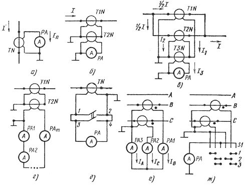
Rice. 1. Circuits for switching on ammeters through a current transformer: a — simple, b — with an intermediate transformer, c — for measuring currents exceeding the rated current of the transformer, d — with an intermediate transformer, with several ammeters, e — with an ammeter switch , c — c three-phase circuit with three ammeters, w — the same with one ammeter with a switch.
The simplest and most common scheme for measuring current with a transformer in the circuit is shown in fig. 1, a.
Current measured with this circuit Az = (AzTn1 NS Azn x n) / (ITn2NS H) = ktn NS n NS dHC,
where AzTn1 and AzTn2 — nominal primary and secondary currents of the current transformer; ktn = It1 / It2 —transformation coefficient; dn = Ip / N — device constant; D = Dn x k x tn — constant of the measuring circuit, n — readings of the instruments in divisions of scales, H — the number of divisions marked on the scale of the device, Azn is the current of the full deflection of the arrow.
The accuracy class of the transformer is selected according to the accuracy class of the measuring device in accordance with the table. 1.
An example. Let the RA ammeter have a scale with N = 150 divisions and a measurement limit Azn = 2.5A. In the measuring circuit of fig.1, and is connected through a current transformer with nominal primary and secondary currents AzTn1 = 600 A and AzTn2 — 5 A respectively. When measuring the current, the needle of the measuring device stopped against division n = 104.
Find the measured current. To do this, we first define the device constant: dn = Ip / N = 2.5 / 100 = 0.025 A / del
Then the circuit constant with measuring transformer and instrument D = (AzTn1/AzTn2)dn = (600 x 0.25) / 5 = 3 A / del.
The measured current is found as a result of multiplying the circuit constant by the number of divisions indicated by the device arrow: I = nD = 104 x 3 = 312 A.
When measuring the current remotely, when the length of the connecting wires between the current transformer and the ammeter exceeds 10 m, or for the simultaneous repetition of readings in different places, it is necessary to include a load in the secondary winding of the current transformer, the resistance of which exceeds the permissible value. in this case, use the diagrams shown in fig. 1, b, c, in which an intermediate current transformer with a primary current of 5 A and a secondary current of 1 or 0.3 A.
In the first case, the load resistance of the secondary winding of the intermediate transformer can be increased to 30 ohms, and in the second - to 55 ohms. To determine the current using this circuit, the current value must be multiplied by the transformation ratio of the intermediate current transformer.
If, when conducting tests in installations up to 1000 V, it is necessary to include a current transformer in the secondary circuit, then the scheme shown in fig. 17, d, which uses random double pole switch… After closing the secondary winding of the transformer, you can make the necessary switching at points 3 and 4 of the circuit. The secondary winding for all switching operations is closed through the switch contact connected to points 1 and 2. Switching in the main circuit of the current transformers takes place only when the voltage is removed.
To measure a current exceeding the rated current of a current transformer, the circuit shown in fig. 1, v... Current transformers T1n and T.2N included so that only half of the current flows through the primary windings Az... The secondary windings of these transformers are included in the primary winding of the intermediate transformer T3N, measuring the sum of the secondary currents of the transformers T1N and T2N, and the ammeter -in the secondary winding of the intermediate transformer.
The primary winding of the intermediate transformer must be calculated for the sum of the secondary currents of the transformers T1N and T2N. Then the relation I = (kt1n + kt2n) NS kt3n NS дн x н = Dn, where all notations correspond to those given earlier.
Sometimes during testing it is necessary to measure the current in three-phase three- and four-wire networks. In three-wire three-phase circuits without a neutral conductor, measuring circuits with two current transformers are used to measure the current of each phase (Fig. 1, e).
In this case, the current Ib of phase B flows through the ammeter PA1, the current Ic of phase C passes through the ammeter PA2, and the current Ia = Iw + Ic of phase A through the ammeter TIME. The current measured by each of the devices is found by the expression = (AzTn1 NS Azn x n) / (ITn2NS H) = ktn NS n NS dn = Dn.
When testing three-phase electric machines for measuring current in phases, a modification of this circuit is more often used, characterized by the presence of switch S1 (Fig. 1, g). The switch allows you to use only one ammeter and reduce the error in measuring the current in the phases, eliminating the difference in the readings of the instruments within their accuracy class. The contacts of this switch must ensure continuous switching of the secondary circuits of the current transformers.