Magnetic detection of defects: principle of operation and application, scheme and device of the defectoscope
The magnetic or magnetic powder defect detection method is used to analyze ferromagnetic parts for the presence of defects such as surface cracks or voids, as well as foreign inclusions located near the metal surface.
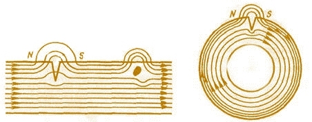
The essence of magnetic detection of defects as a method is to fix the scattered magnetic field on the surface of the part near the place where the defect is inside, while the magnetic flux passes through the part. Since at the site of the defect magnetic permeability changes abruptly, then the magnetic field lines seem to bend around the defect location, thus giving its position.
Surface defects or defects located at a depth of up to 2 mm below the surface "push" the magnetic field lines beyond the surface of the part, and a locally scattered magnetic field is formed at this location.
The use of ferromagnetic powder helps to fix the scattered field, since the poles appearing at the edges of the defect attract its particles. The precipitate formed has the shape of a vein, many times larger than the size of the defect. Depending on the strength of the applied magnetic field, as well as the shape and size of the defect, a certain form of precipitate is formed from its location.
The magnetic flux passing through the workpiece encountering a defect, for example a crack or a shell, changes its magnitude because magnetic permeability of the material in this place turns out to be different than in the rest, therefore the dust settles on the edges of the defect area during magnetization.
Magnetite or iron oxide Fe2O3 powders are used as magnetic powders. The first has a dark color and is used for the analysis of light parts, the second has a brownish-red color and is used to detect defects on parts with a dark surface.
The powder is quite fine, its grain size is from 5 to 10 microns. A suspension based on kerosene or transformer oil, with a ratio of 30-50 grams of powder per 1 liter of liquid, makes it possible to successfully conduct magnetic defects.
Since the defect can be located inside the part in different ways, the magnetization is done in different ways. To clearly identify a crack located perpendicular to the surface of the workpiece or at an angle of no more than 25 °, use pole magnetization of the part in the magnetic belt of the coil with current or place the part between two poles a strong permanent magnet or electromagnet.
If the defect is located at a sharper angle to the surface, that is, almost along the longitudinal axis, then it can be clearly identified by transverse or circular magnetization, in which the magnetic field lines form closed concentric circles, for this the current passes directly through the part or through a non-magnetic metal rod inserted into a hole in the part to be tested.
To detect defects in different directions, combined magnetization is used, in which two magnetic fields act simultaneously perpendicularly: transversely and longitudinally (pole); a circulating magnetizing current also passes through the portion placed in the current coil.
As a result of the combined magnetization, the magnetic lines of force form a kind of bends and make it possible to detect defects in different directions inside the part near its surface. For combined magnetization, an applied magnetic field is used, and pole and circular magnetization are used in both the applied magnetic field and the magnetic field of the remanent magnetization.
The use of an applied magnetic field makes it possible to detect defects in parts made of soft magnetic materials such as many steels, and the residual magnetic field is applicable to hard magnetic materials such as high carbon and alloy steels.
After detecting defects, the parts are demagnetized by alternating magnetic field… Thus, the direct current is used directly for the defect detection process and the alternating current for demagnetization. Magnetic defectoscopy allows detection of defects located no deeper than 7 mm from the surface of the examined part.
To perform magnetic defects on parts made of non-ferrous and ferrous metals, the value of the required magnetizing current in an applied magnetic field is calculated in proportion to the diameter: I = 7D, where D is the diameter of the part in millimeters, I is the strength of the current. For analysis in the remanent magnetization region: I = 19D.
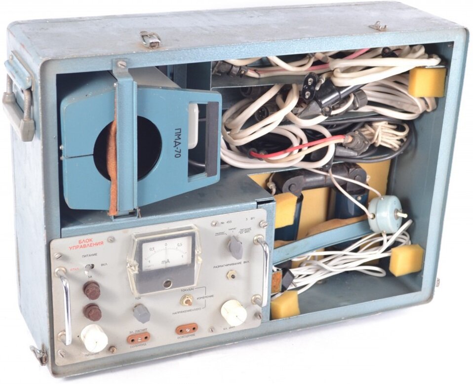
Portable flaw detectors of the PMD-70 type are widely used in industry.
This is a universal flaw detector. It consists of a power supply section including a step-down transformer 220V to 6V with a power of 7 kW, as well as autotransformer and another transformer 220V to 36V, from switching, measuring, control and signaling devices, from magnetizing part including movable contact, contact pad, remote contacts and coil, from slurry bath.
When the switch B is closed, through contacts K1 and K2, current is supplied to the AT autotransformer. The autotransformer AT feeds the step-down transformer T1 220V to 6V, from the secondary winding of which the rectified voltage is supplied to the clamping magnetizing contacts H, to the manual contacts P and to the coil installed in the clamping contacts.
Since transformer T2 is connected in parallel with the autotransformer, then when switch B is closed, current will also flow through the primary winding of transformer T2. Signal lamp CL1 indicates that the device is connected to the network, signal lamp CL2 indicates that the power transformer T1 is also switched on. Switch P has two possible positions: in position 1 — long-term magnetization to detect defects in an applied magnetic field, in position 2 — instantaneous magnetization in the residual magnetization field.
According to the scheme of the PMD-70 flaw detector:
B — packet switch, K1 and K2 — contacts of magnetic starter, RP1 and RP2 — contacts, P — switch, AT — autotransformer, T1 and T2 — step-down transformers, KP — control coil of magnetic starter, KR — intermediate relay coil, VM — magnetic switch, SL1 and SL2 — signal lamps, R — manual magnetizing contacts, H — magnetizing clamp contacts, M — microswitch, A — ammeter, Z — bell, D — diode.
When the switch P is in position 1, the microswitch M closes, the control coil of the magnetic starter KP is connected to the transformer T1, the secondary winding of which supplies it and the contacts of the intermediate relay RP1. The circuit turns out to be closed. The starting device causes the contacts K1 and K2 to close, the power section and with it the magnetizing devices receive power.
When switch P is in position 2, the coil of the intermediate relay KR turns on in parallel with the starter coil. When the microswitch is closed, the short-circuit contact closes, which causes the intermediate relay to turn on, the RP2 contacts close, the RP1 contacts open, the magnetic starter disconnects, and the K1 and K2 contacts open. The process takes 0.3 seconds. Until the microswitch closes, the relay will remain off because the short circuit contact blocks the RP2 contacts. After opening the microswitch, the system returns to its original state.
The current of the magnetizing devices can be adjusted using the AT autotransformer, adjusting the current value from 0 to 5 kA. When magnetized, the bell emits 3 beeps.If the magnetizing current flows continuously, the signal will be continuous and the SL2 signal lamp will operate in the same mode. In the case of short-term power supply, the bell and the lamp will also work for a short time.