The power factor of the induction motor — what it depends on and how it changes
 On the nameplate (data plate) of each induction motor, in addition to other operating parameters, its parameter is indicated as cosine phi — cosfi… Cosine phi is also called induction motor power factor.
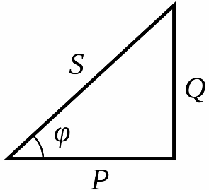
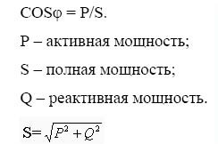
Why is this parameter called cos phi and how is it related to power? Everything is quite simple: phi is the phase difference between current and voltage, and if you graph the active, reactive and total power that occurs during operation of an induction motor (transformer, induction furnace, etc.), it turns out that the ratio of active power to full power — this is cosine phi — Cosphi, or in other words — power factor.
At rated supply voltage and at rated shaft load of an induction motor, the cosine phi or power factor will simply be equal to its nameplate value.
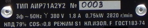
For example, for the AIR71A2U2 engine, the power factor will be 0.8 with a shaft load of 0.75 kW.But the efficiency of this motor is 79%, therefore the active power consumed by the motor at the rated shaft load will be more than 0.75 kW, namely 0.75 / Efficiency = 0.75 / 0.79 = 0.95 kW.
Nevertheless, at rated shaft load, the power parameter or Cosphi is related precisely to the energy consumed by the network. This means that the total power of this motor will be equal to S = 0.95 / Cosfi = 1.187 (KVA). Where P = 0.95 is the active power consumed by the motor.
In this case, the power factor or Cosphi is related to the motor shaft load, because with different shaft mechanical power, the active component of the stator current will also be different. So, in idle mode, that is, when nothing is connected to the shaft, the power factor of the motor will not exceed, as a rule, 0.2.
If the shaft load begins to increase, then the active component of the stator current will also increase, therefore the power factor will increase, and at a load close to the nominal it will be approximately 0.8 — 0.9.
If now the load continues to increase, that is, to load the shaft above the nominal value, then the rotor will slow down, increase slip s, the inductive resistance of the rotor will start to contribute and the power factor will start to decrease.
If the motor is idling for a certain part of the operating time, then you can resort to reducing the applied voltage, for example, switching from a delta to a star, then the phase voltage of the windings will decrease by a root of 3 times , the inductive component from the idle rotor will decrease , and the active component in the stator windings will increase slightly. Thus, the power factor will increase slightly.
In principle, systems driven by alternating current, such as asynchronous motors, always have, in addition to the active, inductive and capacitive components, therefore, every half cycle, a certain part of the energy is returned to the network, the so-called reactive power Q.
This fact creates problems for electricity suppliers: the generator is forced to supply full power S to the grid, which returns to the generator, but the wires still need a suitable cross-section for this full power, and of course there is parasitic heating of the wires from the reactive current circulating back and forth... It turns out that the generator is required to deliver full power, some of which is basically useless.
In a purely active form, the generator of the power plant could supply much more electricity to the user and for this it is necessary that the power factor be close to unity, that is, as in a purely active load where Cosphi = 1.
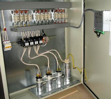
To ensure such conditions, some large enterprises install reactive power compensation units, that is, systems of coils and capacitors that are automatically connected in parallel with asynchronous motors when their power factor decreases.
It turns out that the reactive energy circulates between the induction motor and the given installation, not between the induction motor and the generator in the power station. Thus, the power factor of asynchronous motors is brought to almost 1.