Magnetic field of the current-carrying coil
If an electrostatic field exists in the space around stationary electric charges, then in the space around moving charges (as well as around the time-varying electric fields originally proposed by Maxwell) there exists magnetic field… This is easy to observe experimentally.
Thanks to the magnetic field, electric currents interact with each other, as well as permanent magnets and currents with magnets. Compared to the electric interaction, the magnetic interaction is much stronger. This interaction was studied in due course by André-Marie Ampère.
In physics, the magnetic field characteristic is magnetic induction B and the larger it is, the stronger the magnetic field. The magnetic induction B is a vector quantity, its direction coincides with the direction of the force acting on the north pole of a conventional magnetic arrow placed at some point in the magnetic field — the magnetic field will orient the magnetic arrow in the direction of vector B , that is, in the direction of the magnetic field .
Vector B at any point of the magnetic induction line is directed to it tangentially. That is, the induction B characterizes the force effect of the magnetic field on the current. A similar role is played by the force E for the electric field, which characterizes the strong action of the electric field on the charge.
The simplest experiment with iron filings allows you to clearly demonstrate the phenomenon of the action of a magnetic field on a magnetized object, because in a constant magnetic field small pieces of a ferromagnet (such pieces are iron filings) are magnetized along the field , magnetic arrows, like small arrows of compass.
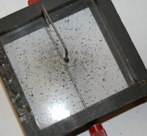
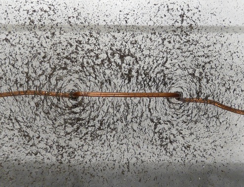
If you take a vertical copper wire and run it through a hole in a horizontally placed sheet of paper (or Plexiglas or plywood) and then pour metal filings onto the sheet, shake it a bit, and then run a direct current through the wire, it's easy to see how the filings will arrange themselves in the form of a vortex in circles around the wire, in a plane perpendicular to the current in it.
These circles of sawdust will simply be a conventional representation of the lines of magnetic induction B of the magnetic field of a current-carrying conductor. The center of the circles in this experiment will be located exactly in the center, along the axis of the current-carrying wire.
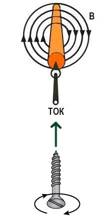
The direction of the magnetic induction vectors in a current-carrying wire is easy to determine by the gimlet rule or according to the right-hand screw rule: with the translational movement of the screw axis in the direction of the current in the wire, the direction of rotation of the screw or gimbal handle (screwing in or out) will indicate the direction of the magnetic field around the current.
Why is the gimbal rule applied? Because the work of the rotor (denoted in field theory by decay) used in two Maxwell equations can be written formally as a vector product (with the operator nabla) and most importantly because the rotor of a vector field can be likened to ( is an analogy) to the angular velocity of rotation of an ideal fluid (as imagined by Maxwell himself), whose flow velocity field represents a given vector field, can be used for the rotor by these rule formulations which are described for the angular velocity .
Thus, if you turn the thumb in the direction of the vector field vortex, it will screw in the direction of the rotor vector of that field.
As you can see, unlike the lines of electrostatic field intensity, which are open in space, the lines of magnetic induction surrounding the electric current are closed. If the lines of electric intensity E begin with positive charges and end with negative charges, then the lines of magnetic induction B simply close around the current that generates them.
Now let's complicate the experiment. Consider instead of a straight wire with current, a bend with current. Suppose that it is convenient for us to position such a loop perpendicular to the plane of the drawing, with the current directed towards us from the left, and from the right towards us. If now a compass with a magnetic needle is placed inside the current loop, then the magnetic needle will indicate the direction of the lines of magnetic induction — they will be directed along the axis of the loop.
Why? Since the opposite sides of the plane of the coil will be analogous to the poles of the magnetic needle.Where the B lines leave is the north magnetic pole, where they enter the south pole. This is easy to understand if you first consider a current-carrying wire and its magnetic field, and then simply wind the wire into a ring.
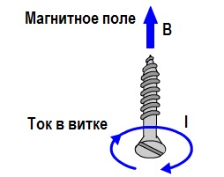
To determine the direction of the magnetic induction of a loop with a current, they also use the gimbal rule or the right-hand screw rule. Place the tip of the gimbal in the center of the loop and rotate it clockwise. The translational movement of the gimbal will coincide in direction with the magnetic induction vector B at the center of the loop.
Obviously, the direction of the current's magnetic field is related to the direction of the current in the wire, be it a straight wire or a coil.
It is generally accepted that the side of the current-carrying coil or coil where the lines of magnetic induction B exit (direction of vector B is outward) is the north magnetic pole and where the lines enter (vector B is directed inward) is the south magnetic pole.
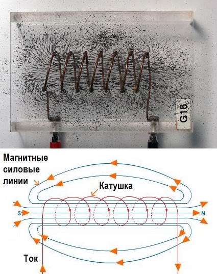
If many turns with current form a long coil - a solenoid (the length of the coil is many times its diameter), then the magnetic field inside it is uniform, that is, the lines of magnetic induction B are parallel to each other and have the same density along the entire length of the coil. Incidentally, the magnetic field of a permanent magnet is externally similar to the magnetic field of a current-carrying coil.
For a coil with current I, length l, with the number of turns N, the magnetic induction in a vacuum will be numerically equal to:
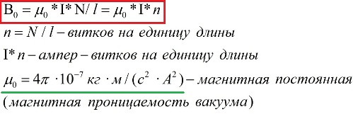
So, the magnetic field inside the coil with the current is uniform and directed from the south pole to the north pole (inside the coil!). The magnetic induction inside the coil is modulo proportional to the number of ampere-turns per unit length of the current-carrying coil.