Input and output filters for a frequency converter — purpose, principle of operation, connection, characteristics
Frequency converters, like many other electronic converters powered by alternating current with a frequency of 50 Hz, only through their device, distort the shape of the consumed current: the current does not depend linearly on the voltage, since the rectifier at the input of the device is usually conventional, that is, uncontrollable . Similarly, the output current and voltage of the frequency converter — they also differ in a distorted form, the presence of many harmonics due to the operation of the PWM inverter.
As a result, in the process of regularly feeding the stator of the motor with such a distorted current, its insulation ages faster, the bearings deteriorate, the noise of the motor increases, the probability of thermal and electrical damage to the windings increases. And for the power supply from the network frequency converter, this state of affairs is always fraught with the presence of interference that can damage other equipment powered by the same network.
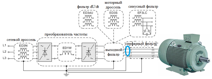
To get rid of the problems described above, additional input and output filters are installed to frequency converters and motors, which save both the power network itself and the motor powered by this frequency converter from harmful factors.
The input filters are designed to suppress the noise generated by the rectifier and the PWM inverter of the frequency converter, thereby protecting the network, and the output filters are designed to protect the motor itself from the noise generated by the PWM inverter of the frequency converter. The input filters are chokes and EMI filters, and the output filters are common mode filters, motor chokes, sine filters, and dU/dt filters.
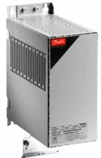
Linear choke
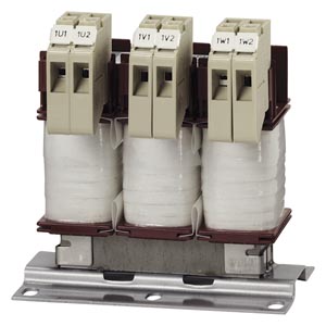
The choke connected between the mains and the frequency converter is throttle line, it serves as a kind of buffer. The linear choke does not pass the higher harmonics (250, 350, 550 Hz and more) from the frequency converter to the network, while protecting the converter itself from voltage spikes in the network, from current surges during transients in the frequency converter, etc. .n.
The voltage drop in such a choke is about 2%, which is optimal for normal operation of the choke in combination with a frequency converter without the function of regenerating electricity during engine shutdown.
So, network chokes are installed between the network and the frequency converter under the following conditions: in the presence of noise in the network (for various reasons); with phase imbalance; when powered by a relatively powerful (up to 10 times) transformer; if several frequency converters are fed from one source; if the capacitors of the KRM installation are connected to the grid.
The linear choke provides:
-
protection of the frequency converter from overvoltages and phase imbalance;
-
protection of circuits from high short-circuit currents in the motor;
-
extending the service life of the frequency converter.
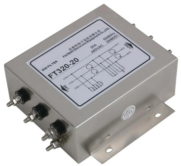
EMP filter
Due to the fact that a motor driven by a frequency converter is essentially a variable load, its operation is associated with the inevitable appearance of high-frequency pulses in the mains voltage, fluctuations that contribute to the generation of parasitic electromagnetic radiation from the supply cables, especially if these cables are of considerable length. Such radiation may damage some devices in the vicinity.
Only an EMF filter is required to eliminate radiation to ensure electromagnetic compatibility with radiation-sensitive devices.
The three-phase electromagnetic radiation filter is designed to suppress interference in the range of 150 kHz to 30 MHz according to the Faraday cell principle. The EMI filter should be connected as close as possible to the input of the frequency converter to provide the surrounding devices with reliable protection against all PWM interference. Sometimes an EMP filter is already built into the frequency converter.
DU / dt filter
The so-called dU / dt filter is a three-phase L-shaped low-pass filter consisting of circuits of inductors and capacitors. Such a filter is also called a motor choke and may often have no capacitors at all and the inductance will be significant. The filter parameters are such that all disturbances at frequencies above the switching frequency of the PWM inverter switches of the frequency converter are suppressed.
If the filter contains capacitors, then the capacitance value of each of them is within a few tens of nanofarads, and inductance values — up to several hundred microhenries. As a result, this filter reduces the peak voltage and impulses at the terminals of a three-phase motor to 500 V / μs, which saves the stator windings from damage.
So if the drive experiences frequent regenerative braking, was not originally designed to work with a frequency converter, has a low insulation class or short motor cable, is installed in a severe operating environment or is used at 690 volts, dU / dt A filter is recommended between the frequency converter and the motor.
Although the voltage supplied to the motor from the frequency converter may be in the form of bipolar square pulses rather than a pure sine wave, the dU / dt filter (with its small capacitance and inductance) acts on the current in such a way that it does in the winding motor almost exactly sinusoidal… It is important to understand that if you use a dU / dt filter at a frequency higher than its nominal value, the filter will overheat, that is, it will bring unnecessary losses.
Sine filter (sine filter)
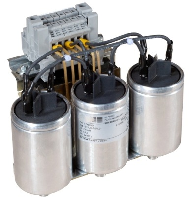
The sine wave filter is similar to a motor choke or dU / dt filter, but the difference lies in the fact that here the capacitances and inductances are large, so the cutoff frequency is less than half the switching frequency of PWM inverter switches. Thus, a better smoothing of high-frequency disturbances is achieved, and the shape of the voltage on the motor windings and the shape of the current in them turns out to be much closer to the ideal sinusoidal.
The capacitances of the capacitors in the sinusoidal filter are measured in tens and hundreds of microfarads, and the inductance of the coils is measured in units and tens of millimeters. Therefore, the sine wave filter is large compared to the dimensions of a conventional frequency converter.
The use of a sine filter makes it possible to use together with a frequency converter even a motor that was originally (according to the specification) not intended for operation with a frequency converter due to poor insulation. In this case, there will be no increased noise, rapid wear of bearings, overheating of windings with high-frequency currents.
It is possible to safely use a long cable between the motor and the frequency converter when they are far apart, while eliminating impulse reflections in the cable that can cause heat loss in the frequency converter.
So, it is recommended to install a sine filter in conditions when:
-
it is necessary to reduce the noise; if the motor has poor insulation;
-
experiences frequent regenerative braking;
-
works in an aggressive environment; connected by a cable longer than 150 meters;
-
should work for a long time without maintenance;
-
during engine operation, the voltage increases step by step;
-
the rated operating voltage of the motor is 690 volts.
It should be remembered that the sinusoidal filter cannot be used with a frequency lower than its nominal value (the maximum permissible deviation of the downward frequency is 20%), so in the settings of the frequency converter it is necessary to set the limit of the frequency below . And the frequency above 70 Hz should be used very carefully and in the settings of the converter, if possible, pre-set the values of the capacitance and inductance of the connected sine filter.
Remember that the filter itself can be noisy and emit a noticeable amount of body, as even at rated load it has about 30 volts dropped on it, so the filter must be installed under suitable cooling conditions.
All chokes and filters must be connected in series with the motor using a shielded cable as short as possible. So, for a 7.5 kW motor, the maximum length of the shielded cable should not exceed 2 meters.
Common Mode Filter — Core
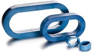
Common mode filters are designed to suppress high frequency noise. This filter is a differential transformer on a ferrite ring (more precisely, on an oval), the windings of which are directly three-phase wires connecting the motor to the frequency converter.
This filter serves to reduce the total currents generated by discharges in the motor bearings. As a result, the common mode filter reduces possible electromagnetic emissions from the motor cable, especially if the cable is not shielded. The three phase conductors pass through the core window and the protective earth conductor remains outside.
The core is fixed to the cable with a clamp to protect the ferrite from the harmful effects of vibrations on the ferrite (the ferrite core vibrates during motor operation). The filter is best mounted on the cable on the terminal side of the frequency converter. If the core heats up to more than 70 ° C during operation, this indicates the saturation of the ferrite, which means that you need to add cores or shorten the cable. It is better to equip several parallel three-phase cables with their own core.