DC machine device
Electric machine with direct current - a machine in which, in a stationary state of operation, electrical energy participates in the process of energy transformation, is effectively DC power.
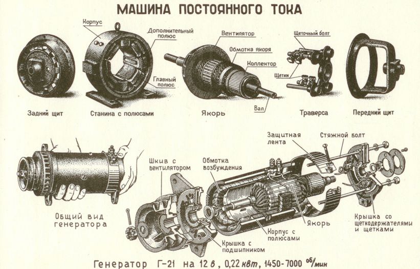
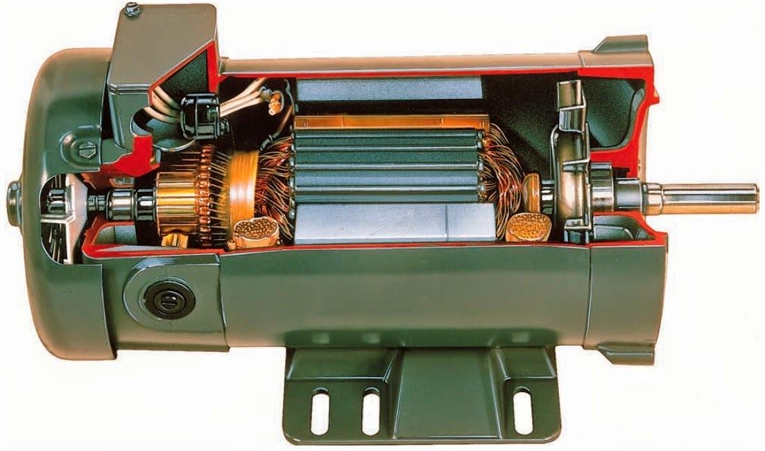
Any electric machine, as a rule, consists of two components: a stationary part - a stator, usually located on the outside, and a rotating internal part - a rotor. The rotor of a modern low and medium power DC machine consists of a shaft and an armature mounted on it, a collector and a fan for cooling the machine.
In low-speed large DC machines, cooling is achieved by an independent fan; in large, high-speed DC machines of open design, sufficient cooling is achieved by the ventilating action of armature rotation. When the machines are closed, external ventilation is used.
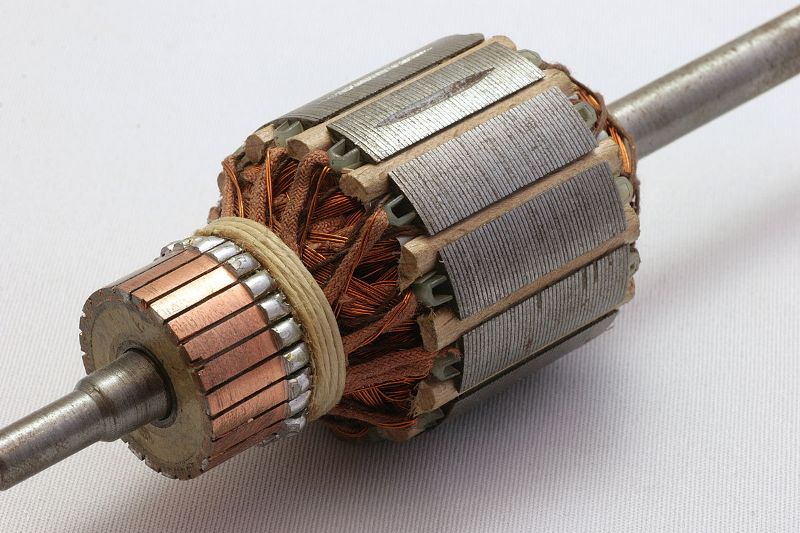
In practice, the term rotor applied to DC machines is not used. All the above rotating parts are called anchor after the main one. Thus, in practice, the term armature has a double meaning: first, the assembly of rotating parts of a DC machine, and second, the armature itself.
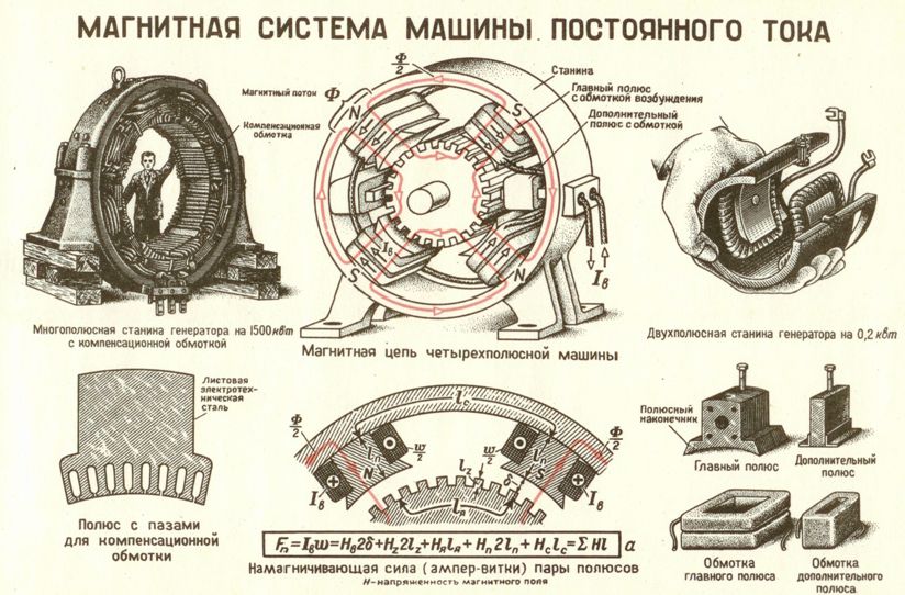
The stator of a modern direct current machine consists of: a yoke, main or main, magnetic poles with magnetizing coils made of insulated or bare copper wire of circular or rectangular cross-section and of additional or switching magnetic poles with magnetizing coils of insulated or bare (with insulating gaskets) copper wire of round or rectangular cross-section.
The term stator as applied to DC machines is not used in practice; the term magnetic system or inductor is used instead. The term yoke is also practically replaced by the term DC machine, since the yoke fulfills this role as a structural part of the machine.
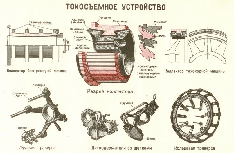
Sliding collector contact
Electric machine collector, which is a rotating part of the collector sliding electrical contact, consists of conductive copper segment plates assembled on a shaft in a cylinder and insulated from each other and from the shaft on which they are fixed. Each collector plate is connected through electrically unevenly distributed points along the coil. The stationary part of the collector contact consists of the same stationary electric machine brushes. The number of brushes is taken according to the number of required branches from the winding.
Characteristics of DC machines
As a single-armature electric machine, the DC collector machine can be parallel, series and series-parallel or mixed excitation.
In a compound excitation machine, the inductor has either a primary inductor winding connected in parallel with the armature winding and an auxiliary excitation winding connected in series with the armature winding, or a primary inductor winding connected in series with the armature winding and an auxiliary excitation winding, connected in parallel with the armature winding.
It is also possible to set up a DC machine with independent excitation. It is obtained if in it the inductor, the exciting coil is disconnected from the armature and connected to an independent source direct current Constant voltage.
DC generators are manufactured either independently excited or self-excited. In independent excitation, the field coil circuit is powered by an independent DC source, i.e. of this generator.
The power of such an auxiliary generator, called an exciter, is only a few percent of the power of the generator whose field the coil supplies. If the pathogen is firmly associated with the excitable generator, it is called an attached pathogen.
If the circuit of the excitation coil is connected to the terminals of the generator, then we have a generator with parallel excitation (or parallel excitation generator), or parallel generator. It is commonly called a DC shunt generator.
If the drive coil circuit is connected in series with the armature circuit, then we have a series excitation generator (or series excitation generator) or series generator. Sometimes called Serial DC Generator.
Main parts of the machine
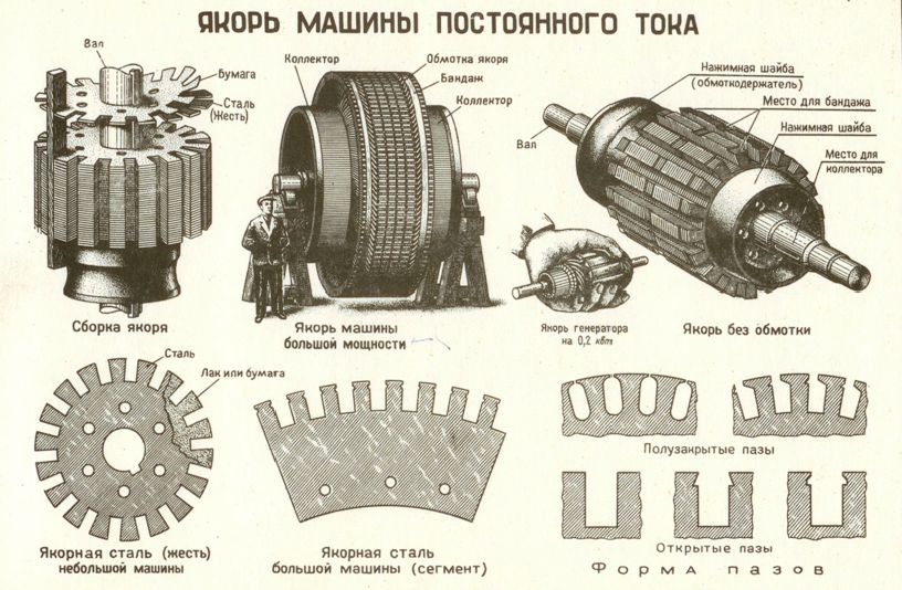
The armature itself is cylindrical in shape, consisting of a large number of disks of special thin sheet electrical steel tightly pressed together.
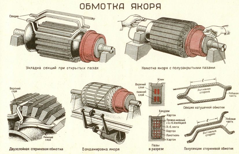
Along the outer circumference of the armature, channels or recesses obtained by stamping are evenly spaced, in which an electric circuit is laid, composed according to certain rules of an insulated copper wire with a round or rectangular cross-section, called an armature winding and strengthened. The armature winding is that part of the DC machine in which the electromotive force is induced and current flows.
The collector has a cylindrical shape and consists of copper plates isolated from each other and from the parts that fix them. The collector plates are electrically connected to specific points on the armature winding, uniformly distributed around the circumference of the armature.
The main or main magnetic poles consist of pole cores and an end part of the pole extended to the armature, called the post or post.
The core and shoe are punched together from sheet electrical steel in the form of appropriately shaped plates, which are then pressed and clamped into a monolithic body. The main magnetic poles create the main magnetic flux of the machine, from the cut of which the rotating armature coil is induced. cars.
Additional magnetic poles, which have a narrow shape and are located in the gaps between the main magnetic poles, are made of rolled steel, sometimes stamped from thin sheets of electrical steel, like the main poles. From the end facing the anchor they are sometimes fitted with a rectangular shoe, with or without chamfers. Additional magnetic poles are used to ensure spark-free operation of the collector.
In large direct current machines designed for severe operating conditions, a number of grooves are punched in the pole shoes of the main magnetic poles, which in this case have a particularly developed shape, to accommodate the compensating winding. It is designed to prevent distortion of the shape of the induction distribution of the main magnetic flux in the space separating the pole shoe from the armature. This space is called the interglandular space or the main gap of the electrical machine.
The compensating coil, like other machine coils, is made of copper and is insulated. The auxiliary pole windings and the compensation winding are connected in series with the armature winding.
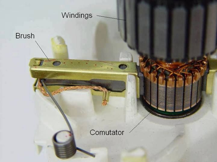
The collector is supported brushes, as a rule, coal, with a rectangular cross-section. They are installed along the lines forming the cylindrical surface of the collector, called switching zones. Usually, the number of attachment zones is the same as the number of machine poles.
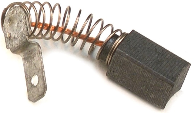
The brushes are inserted into the holders of the brush holders with springs pressing the brushes against the surface of the collector. Brushes of the same set of zones are electrically connected together, and sets of zones of the same polarity (ie across the zone) are electrically connected together and connected to the corresponding external terminal of the machine.
The external clamps of the machine are fixed on a clamping board, which is attached to the yoke of the machine and covered with a protective cover with a hole at the bottom for connecting wires from the electrical network to the clamps. The clamps with a cover form a so-called terminal box.
Often, instead of «zone brush set», the word «brush» is usually said, which means the collection of all brushes of one zone for switching. The collection of all brush zones of a machine forms its complete brush set, commonly called a brush set for short.
Brushes, brush holders, fingers (or clamps) and a traverse (or support) make up the so-called current collector of a DC machine. It also includes connections between zone brush sets of the same polarity.
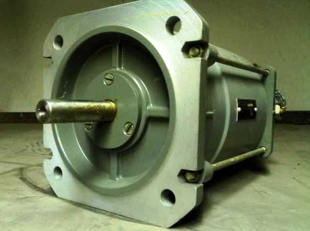
The ends of the machine's armature shaft, called shaft slides, are inserted into bearings. In small and medium-sized machines, the bearings are reinforced in end shields, which at the same time serve to protect the machine from external influences, and also serve to completely enclose the machine if it is closed.
Small DC machines with end shields, as a rule, do not have a foundation plate, they are mounted on bolts that are attached to a concrete or brick foundation, or to the floor, or on special beams called skids.
Sometimes generators, like engines, have only one bearing. The other end of the shaft is flanged or machined to accommodate a coupling half for connection to the free end of the shaft of the drive motor (in the case of a generator) or mechanism (in the case of an engine).