Characteristics of single-phase induction motors
Single-phase asynchronous motors are widely used in technology and everyday life. The production of single-phase asynchronous electric motors from a fraction of a watt to hundreds of watts is more than half of the production of all low-power machines, and their power is constantly increasing.
Single-phase motors are generally divided into two categories:
-
general purpose motors « which include industrial and domestic electric motors;
-
motors of automatic devices — controlled and uncontrolled AC motors and specialized low-power electrical machines (tachogenerators, rotary transformers, selsins, etc.).
A significant proportion of asynchronous electric motors are general-purpose motors that are designed to operate on a single-phase AC network. However, there is a fairly extensive group of universal asynchronous electric motors designed to work in both single-phase and three-phase networks.
The design of universal engines practically does not differ from traditional design of three-phase asynchronous machines… When operating on a three-phase network, these motors have characteristics similar to those of three-phase motors.
Single-phase motors have a squirrel-cage rotor, and the stator winding can be manufactured in different versions. Most often, a working winding filling two-thirds of the slots and a starting winding filling the remaining third of the slots are placed on the stator. The running coil is calculated for continuous operation and the starting coil is calculated only for the starting period. Therefore, it is made of wire with a small cross-section and contains a significant number of turns. To create starting torque, the starting winding includes phase-shifting elements - resistors or capacitors.
Asynchronous motors of low power can be two-phase when the working winding placed on the stator has two phases mixed in space by 90 °. In one of the phases, a phase-shifting element is constantly included — a capacitor or resistor Top, providing a certain phase shift between the coil currents.
It is usually called a motor with a capacitor permanently connected to one of the phases capacitor… The capacitance of the phase-shifting capacitor may be constant, but in some cases the capacitance value may be different for start-up and for run mode.
A characteristic feature of single-phase asynchronous motors is the ability to rotate the rotor in different directions. The direction of rotation is determined by the direction of the initial torque.
At low rotor resistance (Ccr < 1), therefore, a single-phase motor cannot operate in reverse mode. The engine mode corresponds to the rotor revolutions 0 <n <nc at a higher speed the generator mode takes place.
A characteristic of single-phase motors is that its maximum torque depends on the resistance of the rotor. As the active resistance of the rotor increases, the maximum torque decreases and with large resistance values Skr > 1 it becomes negative.
When choosing the type of electric motor to drive a device or mechanism, it is necessary to know its characteristics. The main ones are torque characteristics (initial starting torque, maximum torque, minimum torque), rotation frequency, vibroacoustic characteristics. In some cases, energy and weight characteristics are also required.
As an example, the characteristics of a single-phase motor are calculated with the following parameters:
-
number of phases — 1;
-
mains frequency — 50 Hz;
-
mains voltage — 220 V;
-
active resistance of the stator winding — 5 ohms;
-
inductive resistance of the stator winding — 9.42 Ohm;
-
inductive resistance of the rotor winding — 5.6 Ohm;
-
axial length of the machine — 0.1 m;
-
the number of turns in the stator winding -320;
-
stator hole radius — 0.0382 m;
-
number of channels — 48;
-
air gap — 1.0 x 10³ m.
-
rotor inductance factor 1.036.
The single-phase winding fills two-thirds of the stator slots.
In fig. 1 shows the dependences of the current of a single-phase electric motor and the electromagnetic slip torque. In the ideal idle mode, the motor current consumed by the network, mainly to create a magnetic field, has a relatively large value.
For a simulated motor, the magnitude of the magnetizing current is about 30% of the initial current, for three-phase motors with the same power - 10-15%.The electromagnetic moment in the ideal idle mode has a negative value, which increases as the resistance of the rotor circuit increases. At slipping C= 1, the electromagnetic moment is zero, which confirms the correct operation of the model.
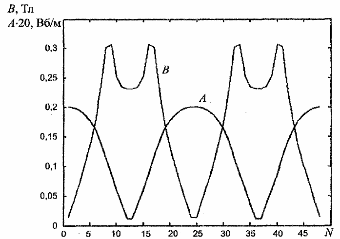
Fig. 1. The envelopes of vector potential and magnetic induction in the motor gap during sliding s = 1
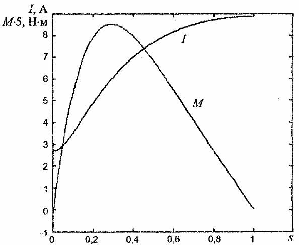
Rice. 2. Dependence of current and electromagnetic torque of a single-phase asynchronous motor on slip
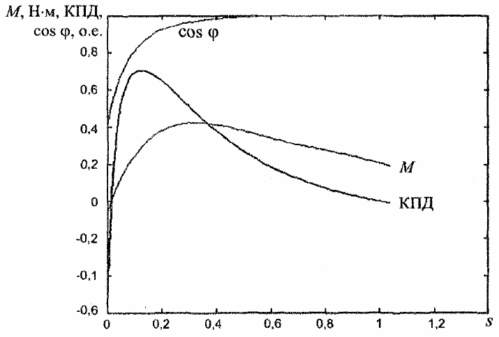
The dependences of useful and consumed power on slip (Fig. 3) have a traditional character. The efficiency of the engine in the ideal idle mode has a negative sign corresponding to the negative torque, and the power factor in this mode is very low (0.125 for the simulated engine).
The lower value of the power factor compared to three-phase motors is explained by the high magnitude of the magnetizing current. As the load increases, the value of the power factor increases and becomes comparable to that of three-phase motors (Fig. 4).
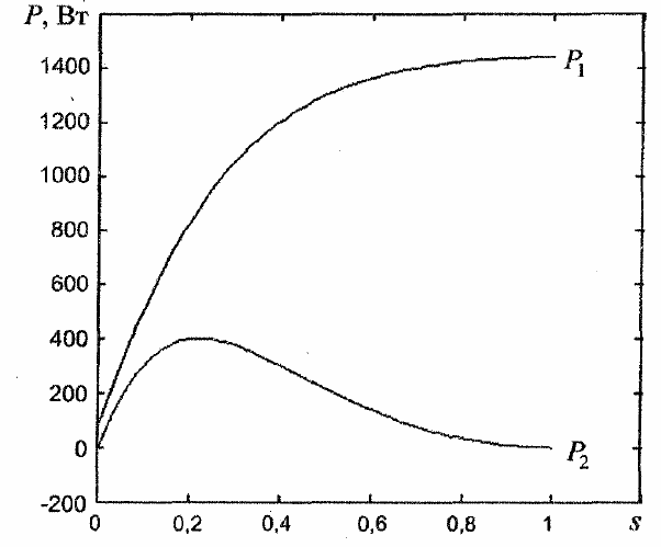
Rice. 3. Dependence of the useful and consumed power of a single-phase asynchronous motor on slip
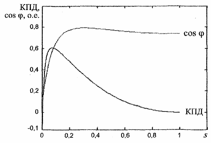
Rice. 4. Dependence of the coefficient of useful action and power of a single-phase asynchronous motor on slip
As the active resistance of the rotor increases, the magnitude of the electromagnetic moment decreases, and at critical slips above unity, it becomes negative.
In fig. 5 shows the dependence of the electromagnetic moment of a single-phase slip motor for different values of the electrical conductivity of the secondary medium of the motor.
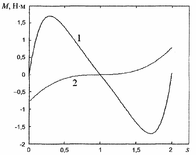
Rice. 5.Dependence of the electromagnetic moment of a single-phase slip motor at different rotor resistances (1 — 17 x 106 Cm / m, 2 — 1.7 x 10⁶ Cm / m)
Capacitor motors have two windings permanently connected to the grid. One of them is connected directly to the network, the second is connected in series with a capacitor that provides the necessary phase shift.
Both windings occupy the same number of slots on the stator, and the number of their turns and the capacitance of the capacitor are calculated in such a way that with some slip a circular rotating magnetic field is provided. Most often, the nominal slip is accepted as such. In this case, however, the initial torque turns out to be much smaller than the nominal one.
The magnetic field in the initial mode is elliptical; the influence of the counter-moving components of the magnetic field is greatly affected. If the capacitance of the capacitor is increased by selecting it from the condition of obtaining a circular field at start-up, then there is a decrease in the torque and a decrease in the energy indicators at nominal slip.
A third variant is also possible, when the circular field corresponds to a slip with a greater magnitude than in the nominal mode. But this path is also not optimal, since the increase in torque is accompanied by a significant increase in losses. An increase in the starting torque of a capacitor motor can be achieved by increasing the active resistance of the rotor. This method leads to an increase in losses with each slip, as a result of which the efficiency of the motor decreases.
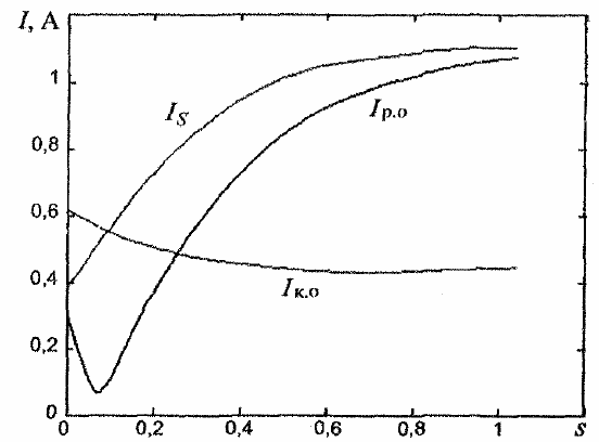
Rice. 6.Dependence of slip capacitor motor currents (Azp.o — operating coil current, Azk.o — capacitor coil current, E — motor current)
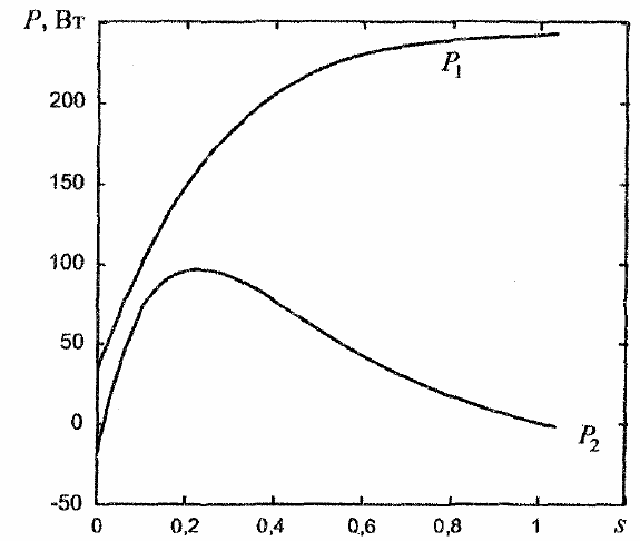
Rice. 7. Dependence on the consumed P1 and useful P2 slip power of a capacitor
Rice. 8. Dependence of the coefficient of useful action and power and the electromagnetic moment of the slip capacitor motor
The capacitor motor has quite satisfactory energy performance, a high power factor, the value of which exceeds the power factor of a three-phase motor, and with increased rotor resistance and significant capacity, high starting torque. At the same time, as mentioned above, the engine has a reduced efficiency value.
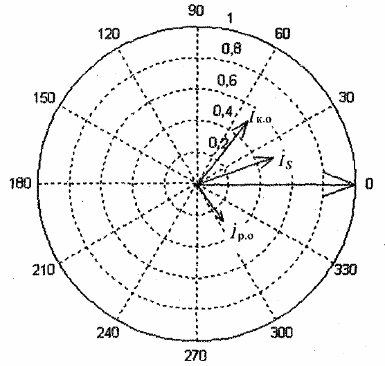
Rice. 9. Vector diagram of a capacitor motor at slip s = 0.1
The vector diagram (Fig. 9) shows that at the selected value of the capacitor capacitance, the capacitor coil current is leading relative to the network voltage, and the working coil current is lagging. The diagram also shows that when sliding close to nominal, the motor's magnetic field is elliptical. To obtain a circular field, the capacitance value of the capacitor must be reduced so that the currents in the two coils are equal in magnitude.
See also on this topic:Multi-speed single-phase capacitor motors