Inductively coupled oscillating circuits
Consider two oscillating circuits positioned relative to each other so that energy can be transferred from the first circuit to the second and vice versa.
Oscillator circuits in such conditions are called coupled circuits, because electromagnetic oscillations occurring in one of the circuits cause electromagnetic oscillations in the other circuit, and energy moves between these circuits as if they were connected.
The stronger the connection between the chains, the more energy is transferred from one chain to another, the more intensely the chains influence each other.
The magnitude of loop interconnection can be quantified by the loop coupling coefficient Kwv, which is measured as a percentage (from 0 to 100%). The circuit connection is inductive (transformer), autotransformer or capacitive. In this article, we will consider inductive coupling, that is, a state when the interaction of the circuits takes place only due to the magnetic (electromagnetic) field.
Inductive coupling is also called transformer coupling because it takes place due to the mutual inductive action of circuit windings on each other, as in in the transformer, with the only difference that the oscillating circuits cannot, in principle, be coupled as closely as can be observed in a conventional transformer.
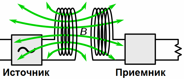
In a system of connected circuits, one of them is powered by a generator (from an alternating current source), this circuit is called a primary circuit. In the figure, the primary circuit is that which consists of the elements L1 and C1. The circuit that receives energy from the primary circuit is called the secondary circuit, in the figure it is represented by elements L2 and C2.
Link configuration and loop resonance
When the current I1 changes in the coil L1 of the primary loop (increases or decreases), the magnitude of the induction of the magnetic field B1 around this coil changes accordingly and the lines of force of this field cross the turns of the secondary coil L2 and therefore, according to the law of electromagnetic induction , induce an EMF in it, which causes the current I2 in the coil L2. Therefore, it turns out that it is through the magnetic field that the energy from the primary circuit is transferred to the secondary, as in a transformer.
Practically connected loops can have a constant or variable connection, which is realized by the method of production of the loops, for example, the coils of the loops can be wound on a common frame, being fixed stationary, or there is the possibility of physical movement of the coils relative to each other, then their relationship is variable. Variable link coils are shown schematically with an arrow crossing them.
Thus, as noted above, the coefficient of coupling of the coils Ksv reflects the interconnection of the circuits as a percentage, in practice, if we imagine that the windings are the same, then it will show how much of the magnetic flux F1 of the coil L1 also falls on coil L2. More precisely, the coupling coefficient Ksv shows how many times the EMF induced in the second circuit is less than the EMF that could be induced in it if all the magnetic lines of force of the coil L1 were involved in its creation.
In order to obtain the maximum available currents and voltages in the connected circuits, they must remain in resonance with each other.
Resonance in the transmission (primary) circuit can be resonance of currents or resonance of voltages, depending on the device of the primary circuit: if the generator is connected to the circuit in series, then the resonance will be in voltage, if in parallel - the resonance of currents. There will normally be voltage resonance in the secondary circuit, as coil L2 itself effectively acts as an AC voltage source connected in series to the secondary circuit.
Having associated loops with a certain CWS, their tuning to resonance is done in the following order. The primary circuit is tuned to obtain resonance in the primary loop, that is, until the maximum current I1 is reached.
The next step is to set the secondary circuit to maximum current (maximum voltage at C2). The primary circuit is then adjusted because the magnetic flux F2 from coil L2 now affects the magnetic flux F1, and the primary loop resonant frequency changes slightly because the circuits are now working together.
It is convenient to have adjustable capacitors C1 and C2 at the same time when setting up connected circuits made as part of a single block (schematically, adjustable capacitors with a common rotor are indicated by the combined dotted arrows crossing them). Another possibility of adjustment is to connect additional capacitors of relatively small capacity in parallel with the main one.
It is also possible to adjust the resonance by adjusting the inductance of the wound coils, for example by moving the core inside the coil. Such "tunable" cores are indicated by dashed lines, which are crossed by an arrow.
The mechanism of action of chains on each other
Why does the secondary circuit affect the primary circuit and how does this happen? The current I2 of the secondary circuit creates its own magnetic flux F2, which partially crosses the turns of the coil L1 and therefore induces in it an EMF, which is directed (according to Lenz's rule) against the current I1 and therefore we seek to reduce it, this seeks the primary circuit as an additional resistance, that is, the introduced resistance.
When the secondary circuit is tuned to the generator frequency, the resistance it introduces into the primary circuit is purely active.
The introduced resistance turns out to be greater, the stronger the circuits, that is, the more Kws, the greater the resistance introduced by the secondary circuit to the primary. In fact, this insertion resistance characterizes the amount of energy transferred to the secondary circuit.
If the secondary circuit is tuned with respect to the frequency of the generator, then the resistance introduced by it will have, in addition to the active one, a reactive component (capacitive or inductive, depending on the direction in which the circuit is branched).
The size of the connection between contours
Consider the graphical dependence of the current of the secondary circuit on the frequency of the generator in relation to the coupling factor Kww of the circuits. The smaller the coupling of the contours, the sharper the resonance, and as Kww increases, the peak of the resonance curve first flattens out (critical coupling), and then, if the coupling becomes even stronger, it acquires a double-backed appearance.
The critical connection is considered optimal from the point of view of obtaining the greatest power in the secondary circuit if the circuits are identical. The coupling factor for such an optimum mode is numerically equal to the attenuation value (the reciprocal of the Q-factor of the circuit Q).
The strong connection (more critical) forms a dip in the resonance curve, and the stronger this connection, the wider the frequency drop. With a strong connection of the circuits, the energy from the primary loop is transferred to the secondary with an efficiency of more than 50%; this approach is used in cases where more power needs to be transferred from circuit to circuit.
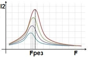
Weak coupling (less than critical) provides a resonance curve whose shape is the same as for a single circuit. Weak coupling is used in cases where there is no need to transfer significant power from the primary loop to the secondary circuit with high efficiency, and it is desirable that the secondary circuit affect the primary circuit as little as possible.The higher the Q-factor of the secondary circuit, the greater the amplitude of the current in it at resonance. The weak link is suitable for measurement purposes in radio equipment.