Application of voltage resonance and current resonance
In an oscillatory circuit of inductance L, capacitance C, and resistance R, free electrical oscillations tend to damp out. To prevent oscillations from damping, it is necessary to periodically replenish the circuit with energy, then forced oscillations will occur, which will not weaken, since the external variable EMF will already support the oscillations in the circuit.
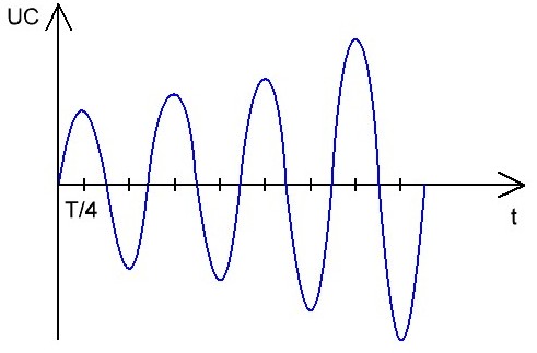
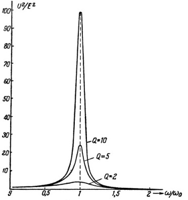
If the oscillations are supported by a source of external harmonic EMF, whose frequency f is very close to the resonant frequency of the oscillating circuit F, then the amplitude of electrical oscillations U in the circuit will increase sharply, i.e. phenomenon of electrical resonance.
AC circuit capacity
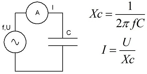
Let us first consider the behavior of the capacitor C in the AC circuit.If a capacitor C is connected to the generator, the voltage U at the terminals of which changes according to the harmonic law, then the charge on the capacitor plates will begin to change according to the harmonic law, similar to the current I in the circuit. The greater the capacitance of the capacitor and the higher the frequency f of the harmonic emf applied to it, the greater the current I.
This fact is related to the idea of the so-called Capacitance of the capacitor XC, which it introduces into the alternating current circuit, limiting the current, similar to the active resistance R, but compared to the active resistance, the capacitor does not dissipate energy in the form of heat.
If the active resistance dissipates the energy and thus limits the current, then the capacitor limits the current simply because it does not have time to store more charge than the generator can give in a quarter period, moreover, in the next quarter of a period, the capacitor releases energy accumulated in the electric field of its dielectric, back to the generator, that is, although the current is limited, the energy is not dissipated (we will neglect the losses in the wires and in the dielectric).
AC inductance
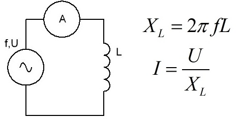
Now consider the behavior of an inductance L in an AC circuit.If, instead of a capacitor, a coil of inductance L is connected to the generator, then when a sinusoidal (harmonic) EMF is supplied from the generator to the terminals of the coil, it will begin to appear an EMF of self-induction, because when the current through the inductance changes, the increasing magnetic field of the coil tends to prevent the current from increasing (Lenz's law), that is, the coil appears to introduce an inductive resistance XL into the AC circuit — in addition to the wire resistance R.
The greater the inductance of a given coil and the higher the frequency F of the generator current, the higher the inductive resistance XL and the smaller the current I because the current simply does not have time to settle because the EMF of the self-inductance of the coil interferes with it. And every quarter of the period, the energy stored in the magnetic field of the coil is returned to the generator (we will ignore the losses in the wires for now).
Impedance, taking R into account
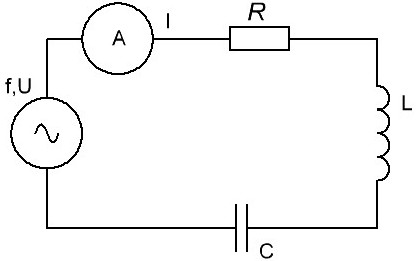
In any real oscillating circuit, the inductance L, the capacitance C and the active resistance R are connected in series.
Inductance and capacitance act on the current in the opposite way in each quarter of the period of the harmonic EMF of the source: on the plates of the capacitor the voltage increases during charging, although the current decreases, and as the current increases through the inductance, the current, although it experiences inductive resistance, but increases and is maintained.
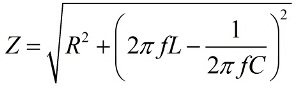
And during the dilution: the discharge current of the capacitor is initially large, the voltage on its plates tends to establish a large current, and the inductance prevents the current from increasing, and the greater the inductance, the less the discharge current will be. In this case, the active resistance R introduces purely active losses. That is, the impedance Z of L, C and R connected in series, at source frequency f, will be equal to:
Ohm's law for alternating current
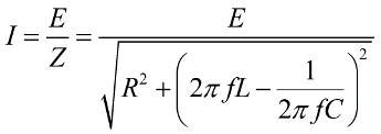
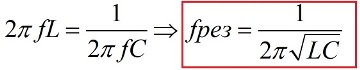
It is obvious from the AC OM law that the amplitude of forced vibrations is proportional to the EMF amplitude and depends on the frequency. The total resistance of the circuit will be the smallest and the amplitude of the current will be the largest, provided that the inductive resistance and the capacitance at a given frequency are equal to each other, in which case resonance will occur. A formula for the resonant frequency of the oscillating circuit is also derived from here:
Voltage resonance
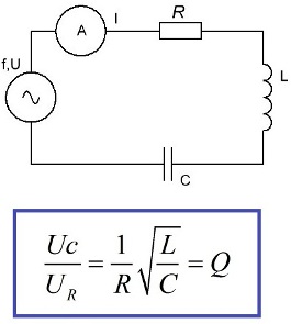
When the EMF source, capacity, inductance and resistance are connected in series, then the resonance in such a circuit is called serial resonance or voltage resonance. A characteristic feature of the resonance of voltage is the significant voltages on capacity and on inductance compared to the ERC of the source.
The reason for the appearance of such a picture is obvious. On the active resistance, according to Ohm's law, there will be a voltage Ur, on the capacitance Uc, on the inductance Ul, and after making the ratio of Uc to Ur, we can find the value of the quality factor Q.The voltage across the capacitance will be Q times the source EMF, the same voltage will be applied to the inductance.
That is, the voltage resonance leads to an increase in the voltage on the reactive elements by a factor of Q, and the resonant current will be limited by the EMF of the source, its internal resistance and the active resistance of the circuit R. Thus, the resistance of the series circuit at the resonant frequency is minimal.
Apply voltage resonance
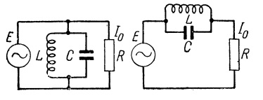
The phenomenon of voltage resonance is used in electrical filters of various types, for example, if it is necessary to remove a current component of a certain frequency from the transmitted signal, then a circuit of a capacitor and an inductor connected in series is placed in parallel with the receiver, so that the resonant frequency current of this LC circuit would be closed through it and they will not reach the receiver.
Then currents of a frequency far from the resonant frequency of the LC-circuit will pass unhindered into the load, and only currents close to the resonance in frequency will find the shortest path through the LC-circuit.
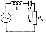
Or vice versa. If it is necessary to pass only a current of a certain frequency, then the LC-circuit is connected in series with the receiver, then the signal components at the resonance frequency of the circuit will pass to the load almost without loss, and the frequencies far from the resonance will be significantly weakened and we can say that they will not reach the load at all. This principle is applicable to radio receivers where a tunable oscillating circuit is tuned to receive a strictly defined frequency of the desired radio station.
In general, voltage resonance in electrical engineering is an undesirable phenomenon because it causes overvoltage and equipment damage.
A simple example is a long cable line, which for some reason turned out not to be connected to the load, but at the same time it is fed by an intermediate transformer. Such a line with distributed capacitance and inductance, if its resonant frequency coincides with the frequency of the supply network, will simply be cut off and fail. To prevent cable damage from accidental resonant voltage, an additional load is applied.
But sometimes voltage resonance plays into our hands, not just radios. For example, it happens that in rural areas the voltage in the network has dropped unpredictably and the machine needs a voltage of at least 220 volts. In this case, the phenomenon of voltage resonance saves.
It is enough to include several capacitors per phase in series with the machine (if the drive in it is an asynchronous motor), and thus the voltage on the stator windings will rise.
Here it is important to choose the right number of capacitors so that they exactly compensate for the voltage drop in the network with their capacitive resistance together with the inductive resistance of the windings, that is, by slightly approaching the circuit to resonance, you can increase the voltage drop even under load.
Resonance of currents
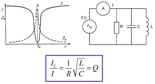
When the EMF source, capacitance, inductance and resistance are connected in parallel with each other, then resonance in such a circuit is called parallel resonance or current resonance.A characteristic feature of current resonance is the significant currents through the capacitance and inductance compared to the source current.
The reason for the appearance of such a picture is obvious. The current through the active resistance according to Ohm's law will be equal to U / R, through the capacitance U / XC, through the inductance U / XL and by composing the ratio of IL to I, you can find the value of the quality factor Q. The current through the inductance will be Q times the source current, the same current will flow every half period into and out of the capacitor.
That is, the resonance of the currents leads to an increase in the current through the reactive elements by a factor of Q, and the resonant EMF will be limited by the emf of the source, its internal resistance and the active resistance of the circuit R. Thus, at the resonance frequency, the resistance of the parallel oscillating circuit is maximum.
Application of resonant currents
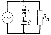
Like voltage resonance, current resonance is used in various filters. But connected to the circuit, the parallel circuit acts in the opposite way than in the case of the series one: installed in parallel with the load, the parallel oscillating circuit will allow the current of the resonant frequency of the circuit to pass into the load, because the resistance of the circuit itself at its own resonant frequency is maximum.
Installed in series with the load, the parallel oscillating circuit will not transmit the resonant frequency signal, because all the voltage will fall on the circuit, and the load will have a small part of the resonant frequency signal.
So, the main application of current resonance in radio engineering is the creation of a large resistance for a current of a certain frequency in tube generators and high-frequency amplifiers.
In electrical engineering, current resonance is used to achieve a high power factor of loads with significant inductive and capacitive components.
For example, reactive power compensation units (KRM) are capacitors connected in parallel with the windings of asynchronous motors and transformers operating under load below rated.
Such solutions are resorted to precisely in order to achieve resonance of currents (parallel resonance), when the inductive resistance of the equipment is equal to the capacity of the connected capacitors at the frequency of the network, so that the reactive energy circulates between the capacitors and equipment, and not between the equipment and the network; so the grid only emits power when the equipment is charged and consumes active power.
When the equipment is not working, the network turns out to be connected in parallel with the resonant circuit (external capacitors and the inductance of the equipment), which represents a very large complex impedance for the network and allows to reduce power factor.