Alternating current electrical machines
Electric machines are used to convert mechanical energy into electrical energy (AC and DC generators) and vice versa (electric motors).
In all these cases, essentially three main discoveries in the field of electromagnetism are used: the phenomenon of mechanical interaction of currents discovered by Ampere in 1821, the phenomenon of electromagnetic induction discovered by Faraday in 1831, and the theoretical summary of these phenomena made by Lenz (1834) in his well-known law of the direction of the induced current (in fact, Lenz's law predicted the law of conservation of energy for electromagnetic processes).
In order to convert mechanical energy into electrical energy or vice versa, it is necessary to create a relative movement of a conductive circuit with a current and a magnetic field (magnet or current).
In electric machines designed for continuous operation, the rotary motion of the moving part of the machine (the rotor of the alternating current machine) located inside the stationary part (the stator) is used.The coil of the machine that serves to create the magnetic field is called the inductor, and the coil that flows around with operating current is called the armature. Both of these latter terms are also used for DC machines.
To increase the magnetic induction, machine windings are placed on ferromagnetic bodies (steel, cast iron).
All electric machines have the property of reversibility, that is, they can be used both as generators of electrical energy and as electric motors.
Asynchronous motors
Asynchronous motors are used one of the manifestations of electromagnetic induction… In physics courses it is demonstrated as follows:
Underneath a copper disk, which can rotate about a vertical axis passing through its center, is placed a vertical horseshoe magnet driven to rotate about the same axis (the mechanical interaction between the disk and the magnet is excluded). In this case, the disc begins to rotate in the same direction as the magnet, but at a lower speed. If you increase the mechanical load on the disc (for example, by increasing the friction of the axle against the thrust bearing), then its rotation speed decreases.
The physical meaning of this phenomenon is easily explained by the theory of electromagnetic induction: when the magnet rotates, a rotating magnetic field is created, which induces eddy currents in the disk, the magnitude of the latter depends, other things being equal, on the relative speed of the field and the disk .
According to Lenz's law, the disc must rotate in the direction of the field. In the absence of friction, the disk must acquire an angular velocity equal to the velocity of the magnet, after which the induced emf will disappear. In real life, friction is inevitably present and the disc becomes slower.Its magnitude depends on the mechanical braking moment experienced by the disk.
The discrepancy between the speed of rotation of the disk (rotor) and the speed of rotation of the magnetic field is reflected in the name of the motors.
The principle of operation of asynchronous motors:
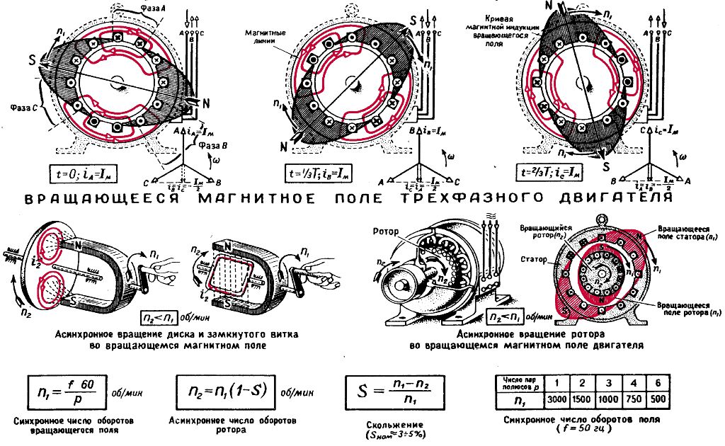
In technical asynchronous motors (most often three-phase) a rotating magnetic field is created polyphase currentflowing around the stationary stator winding. At the frequency of three-phase current is and the number of stator coils 3p rotating field makes n = f / p revolutions / sec.
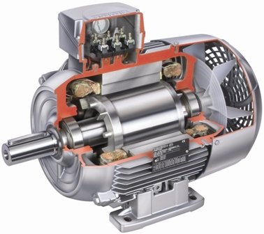
A rotatable rotor is located in the stator cavity. A rotating mechanism can be connected to its shaft. In the simplest "squirrel cell" motors, the rotor consists of a system of longitudinal metal rods placed in the grooves of a steel cylindrical body. The wires are short-circuited by two rings. To increase the torque, the radius of the rotor is made large enough.
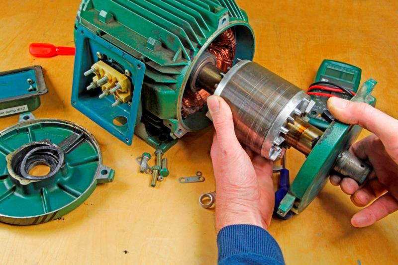
In other motor designs (typically high power motors), the rotor wires form an open three-phase winding. The ends of the coils are short-circuited in the rotor itself, and the leads are brought out to three slip rings mounted on the rotor shaft and isolated from it.
A three-phase rheostat is connected to these rings using sliding contacts (brushes), which serves to start the motor in motion. After the motor is turned, the rheostat is completely removed and the rotor becomes a squirrel cage (see — Asynchronous motors with a wound rotor).
There is a terminal board on the stator housing. The stator windings are brought out to them. They can be included star or triangle, depending on the mains voltage: in the first case the mains voltage can be 1.73 times higher than the second.
The value characterizing the relative deceleration of the rotor compared to the stator field of the induction motor is called slipping… It changes from 100% (at the moment of starting the motor) to zero (ideal case of lossless rotor movement).
The reversal of the direction of rotation of the induction motor is achieved by mutual switching of every two linear conductors of the electrical network supplying the motor.
Squirrel cage motors are widely used in industry. The advantages of asynchronous motors are the simplicity of the design and the absence of sliding contacts.
Until recently, the main disadvantage of such motors was the difficulty in speed regulation, because if the voltage of the stator circuit is changed for this, then the torque changes sharply, but it was technically difficult to change the frequency of the supply current. Modern microprocessor devices are now widely used to control the frequency of the supply current to vary the speed of motors — frequency converters.
Alternators
Alternators are built for significant power and high voltage. Like asynchronous machines, they have two windings. Normally, the armature winding is located in the stator housing. The inductors that create the primary magnetic flux are mounted on the rotor and are powered by an exciter—a small DC generator mounted on the rotor shaft. In high-powered machines, the excitation is sometimes created by a rectified alternating voltage.
Due to the immobility of the armature winding, the technical difficulties associated with the use of sliding contacts at high powers disappear.
The figure below shows a schematic of a single-phase generator. Its rotor has eight poles. On these are wound coils (not shown in the figure) fed from an external source by direct current applied to slip rings mounted on the rotor shaft. The pole coils are wound in such a way that the signs of the poles facing the stator alternate. The number of poles must be even.
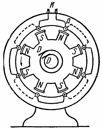
The armature winding is located in the stator housing. Its long working «active» wires, perpendicular to the plane of the drawing, are shown in the figure with circles, they are crossed by the lines of magnetic induction when the rotor rotates.
The circles show the instantaneous distribution of the directions of the induced electric fields. The connecting wires running along the front side of the stator are shown with solid lines, and on the back side with dashed lines. K clamps are used to connect an external circuit to the stator winding. The direction of rotation of the rotor is indicated by an arrow.
If you mentally cut the machine along a radius passing between the clamps K and turn it into a plane, then the relative position of the stator winding and the rotor poles (side and plan) will be depicted with a schematic drawing:
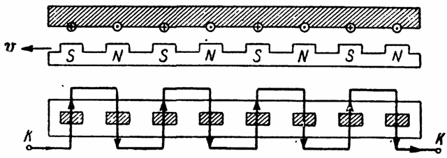
Considering the figure, we make sure that all the active wires (passing through the poles of the inductor) are connected to each other in series and the EMF induced in them is summed. The phases of all EMFs are obviously the same.During one complete rotation of the rotor, four complete periods of current change will be obtained in each of the wires (and therefore in the outer circuit).
If an electrical machine has p pairs of poles and the rotor rotates making n revolutions per second, then the frequency of the alternating current received by the machine is f = pn hz.
Since the frequency of the EMF in the network must be constant, the speed of rotation of the rotors must be constant. To obtain an EMF of technical frequency (50 Hz), a relatively slow rotation can be used if the number of rotor poles is large enough.
To obtain three-phase current, three separate windings are placed in the stator body. Each of them is offset relative to the other two by a third of the arc distance between adjacent (opposite) poles of the inductors.
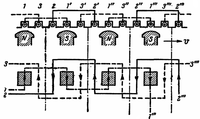
It is easy to verify that when the inductors rotate, EMFs are induced in the coils shifted in phase (in time) by 120 °. The ends of the coils are removed from the machine and can be connected in star or delta.
In a generator, the relative speed of the field and conductor is determined by the diameter of the rotor, the number of revolutions of the rotor per second, and the number of pole pairs.
If the generator is driven by a water current (hydrogenerator), it is usually made with slow revolutions. To obtain the desired current frequency, it is necessary to increase the number of poles, which in turn requires an increase in the diameter of the rotor.
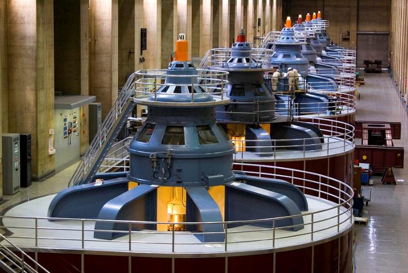
For a number of technical reasons powerful hydrogen generators they usually have a vertical shaft and are located above the hydraulic turbine, which causes them to rotate.
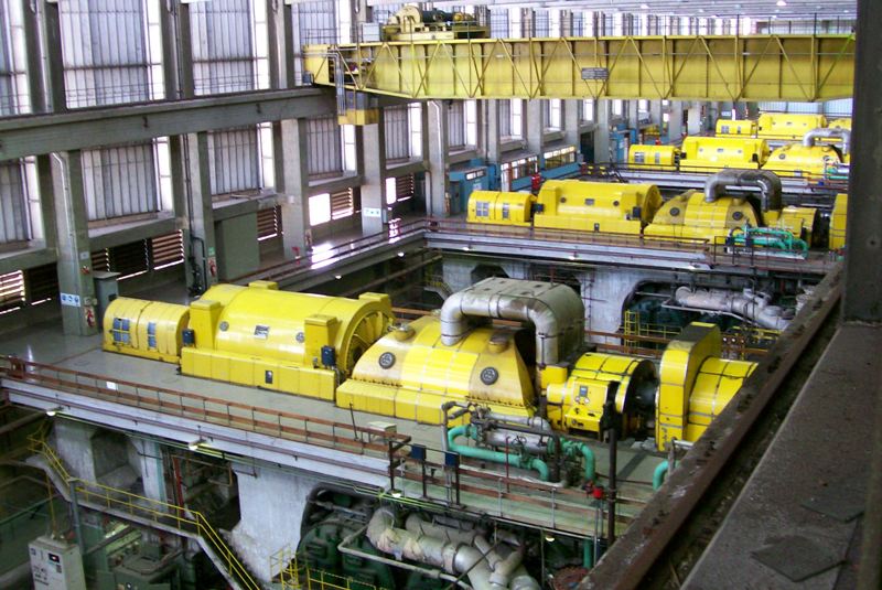
Steam Turbine Driven Generators — Turbine generators are usually high speed. In order to reduce mechanical forces, they have small diameters and a correspondingly small number of poles. A number of technical considerations require the production of turbine generators with a horizontal shaft.
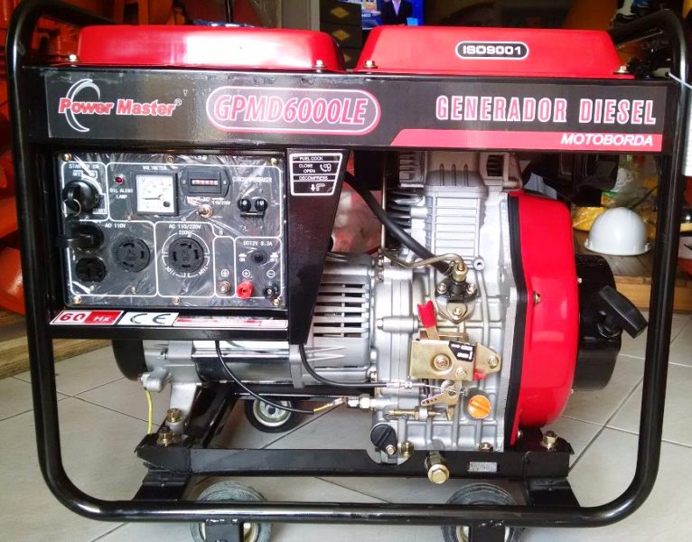
If the generator is driven by an internal combustion engine, it is called a diesel generator, since diesel engines are generally used as engines that consume cheaper fuel.
Generator reversibility, synchronous motors
If an alternating voltage is applied to the stator winding of the generator from an external source, then there will be an interaction of the poles of the inductor with the magnetic field of the current generated in the stator, and torques from the same direction will act on all poles.
If the rotor rotates at such a speed that shortly after half the period of the alternating current, the next pole of the inductor (opposite in sign to the first pole) will fit under the considered wire of the stator winding, then the sign of the interaction force between it and the current , which has changed its direction, will remain the same.
Under these conditions, the rotor, being under the continuous influence of the torque, will continue to move and will be able to drive any mechanism. Overcoming the resistance to the movement of the rotor will occur due to the energy consumed by the network, and the generator will become an electric motor.
It should be noted, however, that continuous movement is possible only at a strictly defined speed of rotation, since in case of deviation from it an accelerating moment will act partially on each of the poles of the rotor, moving between the two conductors of the stator, part of the time - stopping .
Thus, the speed of rotation of the motor must be strictly determined, — the time during which the pole is replaced by the next one must coincide with the half-period of the current, which is why such motors are called synchronously.
If an alternating voltage is applied to the stator winding with a stationary rotor, then, although all the poles of the rotor during the first half-cycle of the current experience the action of torques of the same sign, still, due to inertia, the rotor will not have time to move. In the next half-cycle, the sign of the torques for all rotor poles will change to the opposite.
As a result, the rotor will vibrate but will not be able to rotate. Therefore, the synchronous motor must first be wound up, that is, brought to the normal number of revolutions, and only then the current in the stator winding should be turned on.
The development of synchronous motors is carried out by mechanical methods (at low powers) and special electrical devices (at high powers).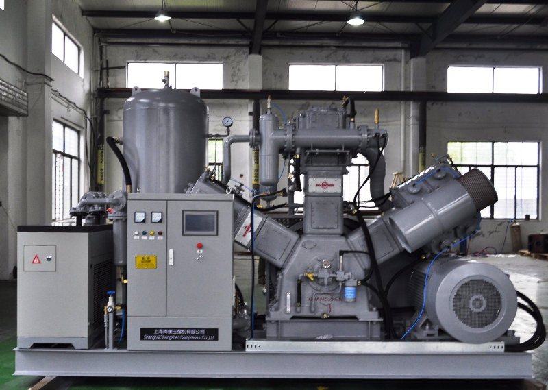
For small load changes, the motor speed will automatically change to adapt to the new load. So, as the load on the motor shaft increases, the rotor immediately slows down. Therefore, the phase shift between the line voltage and the opposite induced EMF induced by the inductor in the stator winding changes.
In addition, the armature reaction creates a demagnetization of the inductors, so the stator current increases, the inductors experience increased torque, and the motor begins to rotate synchronously again, overcoming the increased load. A similar process occurs with load reduction.
With sharp fluctuations in the load, this adaptability of the motor may be insufficient, its speed will change significantly, it will "fall out of synchronism" and eventually stop, while the induction EMF induced in the stator disappears, and the current in it increases sharply. Therefore, sharp fluctuations in the load must be avoided. To stop the motor, obviously you must first disconnect the stator circuit and then disconnect the chokes; when starting the engine, you must adhere to the reverse order of operations.
Synchronous motors are most often used to drive mechanisms that operate at a constant speed. Here are the advantages and disadvantages of synchronous motors and the methods of starting them: Synchronous motors and their applications
Educational film strip - "Synchronous motors", created by the educational-visual aids factory in 1966. You can watch it here: Filmstrip «Synchronous Motor»