Switching devices for manual control and command devices for controlling the electric drive
Electric drive control equipment performs various functions: starting and stopping the engine, reversing, braking and regulating its speed. Some of the electric drive control operations are performed by the operator using manual control devices, which include knife switches, toggle switches, controllers, command controllers, buttons, and universal switches.
Switching is a switching device with cut-type contacts (wedge contacts) and manual actuation for two positions («on», «off»).
Switching — This is a type of switch for two workers and one neutral position for alternating connection to two different electrical circuits.
Switches and blade switches are available in single, double and three pole versions.
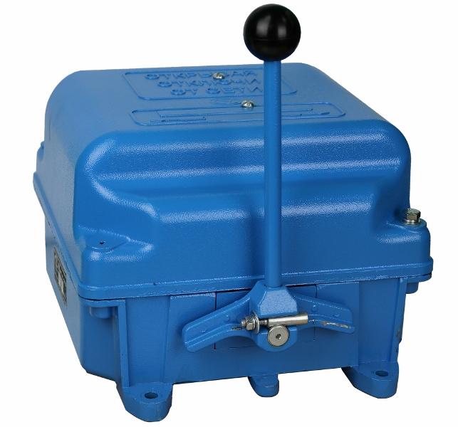
The same functions as circuit breakers are performed by package switches.
See here for more details:
Switches - purpose, types, device, principle of operation
Batch Switches and Switches — Device and Circuits
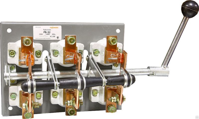
 Circuit breakers (R) and switch-disconnectors (P) with a central handle are produced without arc devices. They are designed to disconnect unloaded electric circuits and create a visible break, for example during repairs and inspections of automatically controlled electric drives.
Side Lever Actuated (RPB) and Center Lever Actuated (RPT) tap-changers and corresponding tap-changers (PPB and PPT) are manufactured with arc chutes and can switch currents within 50-100% of rated (depending on the type and value of the voltage) …
The selection of circuit breakers and switches is made according to the rated current, voltage and construction.
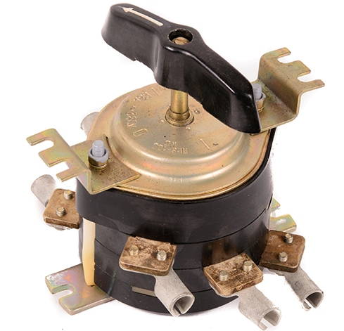
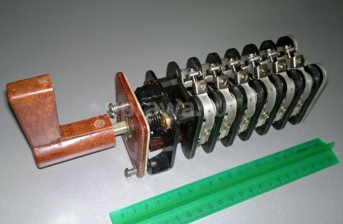
Controller is a multi-stage switching device for direct switching in the main circuits and in the excitation circuits of motors with a voltage of up to 500 V, as well as for changing the resistances of the resistors included in these circuits. Cam controllers are widely used in crane electric drives for AC up to 30 kW and DC up to 20 kW.
In an AC controller, switching is natural, without arcing devices. The switching elements of the DC controller are similar in design, but each has a magnetic blown arc extinguishing device.
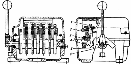
Cam controller KKT60A
The switching elements of the cam controller are located on two plastic rails 3. The main contacts 1 are made of copper. The fixed contacts are fixed directly on the plastic rails, and the movable ones are mounted on the levers 2 with a hinged-spring connection between the lever and the contact.
The washers of the tower 5 are mounted on the shaft of the controller, which is rotated by the handle 6, each of which has a certain profile to create the necessary sequence of switching contacts. When the edge of the cam washer runs over the contact lever roller, the contacts open; when the roller leaves the edge, the lever under the action of the return spring puts the contacts in the closed state. The electrical connection with movable contacts is carried out by a flexible connection 4.
The choice of controller is based on the type and power of the motor it controls. The main parameter of the controller is the rated current of the main circuit at duty cycle = 40% and the total cycle time is no more than 4 minutes.
The rated power of the controller is the power of the motor it controls at rated voltage and current. The limiting power of the cam controller depends on the operating mode of the mechanism and is mainly determined by the wear resistance of the switching contact elements (it decreases with an increase in the number of starts per hour).
To extend the upper power limit of the controlled motors, cam controllers are used together with contactors whose switching properties are much higher than those of the controller contacts.
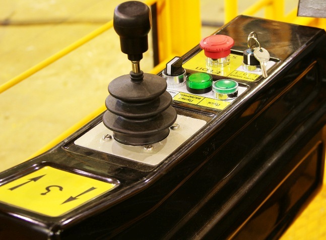
Command apparatus — these are devices that are influenced by an operator or a running machine and that are designed to perform switching in the control circuits of electromagnetic contactors and relays, regulators, amplifiers, converters, etc. Such devices include buttons, switches and control switches, command controllers, moves and limit switches.
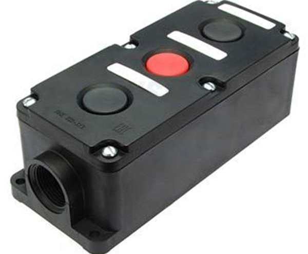
Buttons (push switches) are used for remote control of relatively infrequently started engines to perform simple operations: switching on and off one or two contactors (starters) and separate auxiliary circuits.
A push button control station includes one to three buttons that are not electrically connected to each other; make and break double circuit breaker contacts.
More details here: Modern control buttons and key posts
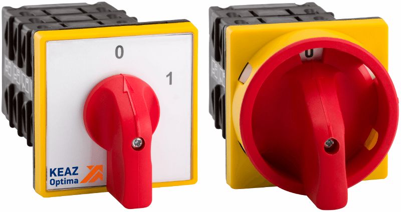
Universal switches are multi-circuit devices for infrequent manual switching of control and automation circuits.
Switches of the UP-5300, UP-5400 series (in a protected version) have relatively powerful contacts (continuous load up to 16 A) and are available with the number of sections from 2 to 16. Each such section contains two contacts that are closed or open from the protrusions of the washer washer, mounted on a common roller, rotating with a handle. A selection of standard washers with different configurations provides a specific program for closing contacts.
Universal switches are produced with the handle returning to its original position and with its fixation in any position. See also: Control switches
Control keys are similar in purpose to universal switches and allow the application of more diverse programs for switching contacts, although the power of the latter is smaller (continuous current 10 A).
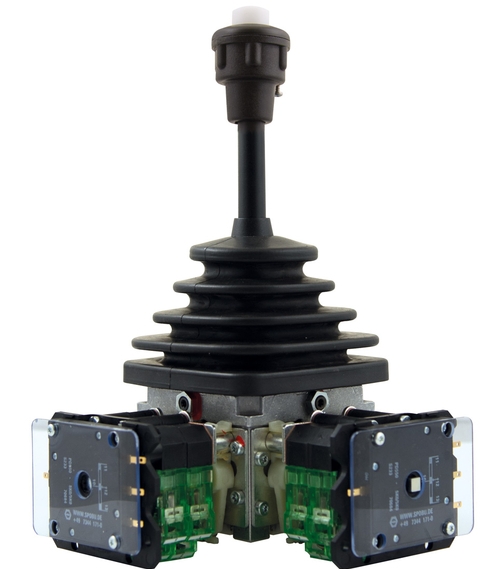
Command controllers — these are devices designed for remote switching in several circuits with relatively low power (maximum included alternating current — 10 A, constant at voltage 220 V and inductive load — 1.5 A).
Two types of command controllers are used: contact and non-contact. The contact controller is a multi-position device with a preset program for closing and opening contacts when turning the drive shaft manually or by mechanical drive.
Travel switches — these are command devices kinematically connected to the working machine and actuated at certain points along the path of its moving parts. Switches are used to automatically close and open the circuit depending on the path and to limit the movement of moving parts in an emergency (limit switches).
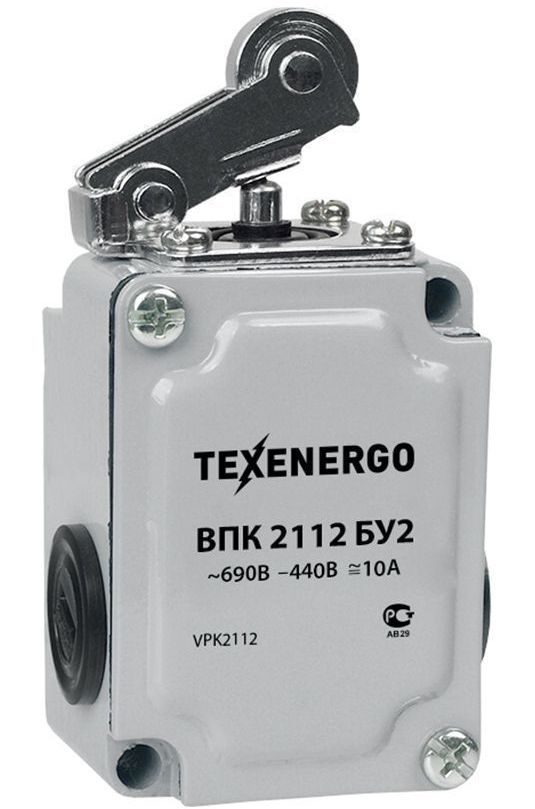
Their main varieties are the following: push (button), lever and rotation. The first two types are mainly used as limit switches.
In a push switch, a half-round head actuator switches a movable contact with contacts. In a switch, the contacts are switched by acting on a roller lever. The rotary limit switch is designed as a cam controller. Its shaft is directly or through a gearbox connected to the shaft of the mechanism.
A significant disadvantage of contact mechanical switches is the possibility of their misalignment with frequent switching and insufficient reliability, especially at high speeds of the mechanism, as well as significant noise and radio interference. In this regard, devices with non-contact elements, inductive and capacitive sensors are now widely used.
See also:
Installation of limit switches and micro switches