Intrinsically safe electrical circuit
Intrinsically safe is such an electric circuit, the very implementation of which, with a probability of no more than 0.1%, will not allow the occurrence of an electric discharge that can cause the ignition of the surrounding explosive environment, which, as a rule, is confirmed by the test conditions. The explosion-proof condition of an «intrinsically safe electrical circuit» is based on maintaining the voltage, current and power in such a circuit at a specified intrinsically safe level. Three levels of intrinsic safety can be distinguished for an intrinsically safe circuit: ia, ib and ic.
Intrinsically safe levels
ya — particularly explosion-proof level. This implies that safe conditions are observed even when two independent or simultaneous circuit faults occur. This level of intrinsic safety guarantees the greatest explosion protection and safety, which is why it is applicable to explosive areas of classes 0, 1 and 2.
ib — explosion-proof level. Only one damage is allowed with this level, so it only applies to Class 1 and 2 hazardous areas.
IC — the level of increased reliability against explosion.In general, it does not allow damage, so it is only used in Class 2 hazardous areas.
Classes of explosive areas
Like the inherent safety levels of circuits, danger zones are also classified:
Explosive zone 0. In such an area, an explosive gas mixture is constantly or for a long time.
Explosive zone 1. In this area, even under normal operating conditions of the equipment, there is always some possibility of an explosive gas mixture around.
Explosive zone 2. An explosive gas mixture is unlikely to be present in this area under normal operating conditions. If this happens, it is extremely rare and then for a short period of time.
Internal factor of safety
For the intrinsically safe circuits used, a special coefficient is introduced - intrinsic safety coefficient. It expresses the ratio of the minimum parameters of the ignition condition to the corresponding parameters of intrinsic safety. Thus, in the United States, the following intrinsically safe factors of protection against explosion of the "intrinsically safe electrical circuit" type are accepted:
Genuine safety factor 1.5 — for one breakdown under the most unfavorable conditions;
Genuine Safety Factor 1 — for two damages under the most unfavorable conditions;
For example, in North America, a power factor of 1.5 is assumed for conditions where the device is experimentally tested. In the course of theoretical studies, for the normal mode and for the emergency mode with one fault, a factor of 2 is taken for current and voltage, and for the emergency mode with two faults, the intrinsic safety factor is taken as 1.33.
The main reason why the intrinsic safety factor increases under these conditions is that in theoretical studies they usually do not have complete information about the nominal values of all components, for example the inductance value can depend on how it is measured.
According to local GOST and European standards, the intrinsic safety factor of an intrinsically safe circuit should not be less than 1.5 for normal operation of electrical equipment, as well as for emergency mode with artificially created damage to connections and other elements of this electrical equipment . For voltage and current, an inherent safety factor of 1.5 corresponds to a factor of 2.25 for energy.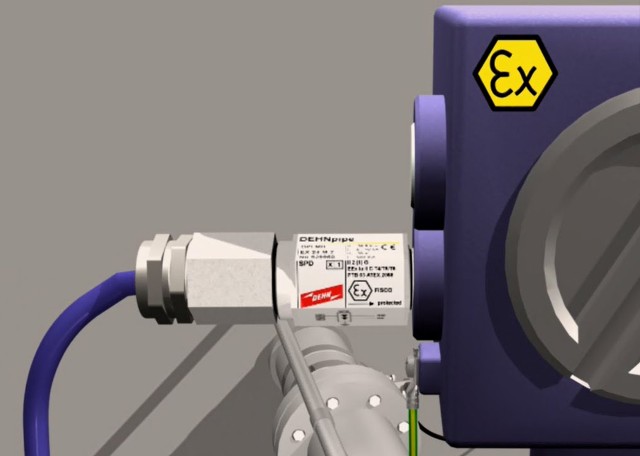 Simple electrical equipment
Electrical equipment has its own classification in terms of intrinsic safety. Simple equipment includes electrical devices or a set of electrical devices of simplified design with certain values of established technical parameters corresponding to the intrinsic safety parameters of the electrical circuit in which they are used.
Such simple electrical equipment includes:
-
1 — passive electrical devices — switches, junction boxes, simple semiconductor devices, resistors;
-
2 — devices that can store energy with electrical parameters that are installed and taken into account when determining their own safety — capacitor, inductor;
-
3 — power generation devices — thermocouples and photocells with a voltage of no more than 1.5 V, a current of no more than 0.1 A, a power of no more than 0.025 W. The inductive and capacitive factors of these devices are taken into account as in paragraph 2.
It is necessary to understand that the simple equipment must meet the requirements of the current scientific and technical documentation for intrinsically safe equipment. So, according to GOST R IEC 60079-11-2010, using simple equipment in intrinsically safe circuits, the following should be taken into account:
1) Simple equipment should not be safe due to current and/or voltage limits.
2) The equipment must not contain any means of increasing voltage or current.
3) Equipment before no-load should be tested with double voltage, at least 500 V.
4) All brackets must meet special requirements.
5) Non-metallic or light alloy sheaths must be electrostatically safe.
6) The temperature class of the equipment must correspond to the working conditions.
In practice, this set of limitations makes it difficult to use simple equipment in intrinsically safe circuits. Points 1 and 2 are usually easy to follow. But points 3 to 6 can already cause difficulties.
For example, although the resistance thermometer is a simple piece of equipment, however, according to GOST 6651-2009, such a device is tested only with a voltage of 250 V and therefore cannot be used in an intrinsically safe circuit (in accordance with paragraph 3). The use of such a device requires a special design of the sensor with adequate strength of its insulation.
According to points 4 and 5, it is not easy to check simple equipment because the necessary information is often not available and it is not possible to carry out the check properly.
Intrinsically safe electrical equipment
Intrinsically safe electrical equipment is called that has intrinsically safe internal and external electrical circuits.External equipment, such as output elements, solenoid valves, current-pressure transducers, when used in a hazardous area, must have an electrical safety certificate. Certification is based on maximum energy level and auto-ignition temperature.
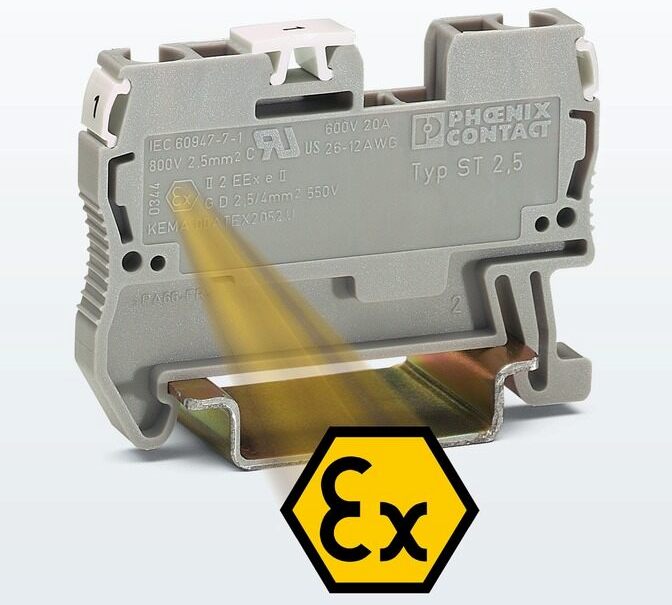
Electrical equipment installed in potentially explosive atmospheres must be appropriately marked with an indication of the intrinsic safety level of the circuit.
Associated electrical equipment
Connected electrical equipment includes circuits of devices and electrical equipment which, during normal or emergency operation, are not galvanically isolated from the intrinsically safe circuit.
Passive and isolated DC barriers, as well as control and measurement equipment used to measure and connect signals received from hazardous areas are the main part of this type of equipment and therefore must have certificates for the maximum value of energy that can be transferred to an explosive area.
The electrical equipment itself is located in a non-explosive area, and if it is necessary to place it in an explosive area, the equipment is equipped with appropriate explosion protection.
European companies put the [Ex ia] IIC mark on connected electrical equipment located in a non-explosive area. The connected electrical equipment, which is located in an explosive area and at the same time has a fire-resistant housing, is marked with Ex «d» [ia] IIC T4. Markings in square brackets reflect the fact that electrical equipment is connected.
Explosion-proof electrical equipment with explosion protection of the "intrinsically safe electrical circuit" type located in a hazardous area must have a certificate for the self-ignition temperature value.
Intrinsically safe mounting characteristics
The installation of electrical installations with intrinsically safe electrical circuits is carried out so that external electric and magnetic fields do not adversely affect their own safety. Sources of external electric and magnetic fields can be power lines passing nearby or high-current conductors. It is helpful to use shields, bend the wires, or physically move the source of the electric or magnetic field away from the installation.
In accordance with point 7.3.117 of the PUE, cables from intrinsically safe electric circuits installed either in an explosive zone or outside it must meet the relevant requirements.
The intrinsically safe cable is separated from all cables in accordance with GOST 22782.5-78. It is unacceptable to use the same cable in an intrinsically safe and an intrinsically safe circuit. HF cables for intrinsically safe circuits must not have loops. In addition, the conductors of intrinsically safe circuits must be protected from grips that could compromise their own safety.
If there are cables from intrinsically safe and intrinsically safe circuits at the same time in one channel or bundle, then it is recommended to separate them with a layer of intermediate insulation or a grounded conductive barrier. It is possible not to separate such cables only if the intrinsically safe or non-intrinsically safe circuits have their own individual shields or metal sheaths.
When laying intrinsically safe cable routes in hazardous areas, it is necessary to comply with other requirements of PUE Ch. 7.3.
When choosing a cable for an explosive area, consider the following PUE requirements:
-
wires must be insulated;
-
only wires with copper wires are used;
-
rubber or PVC insulation is allowed;
-
polyethylene insulation is prohibited; in hazardous areas of classes BI and Bia, the aluminum sheath is excluded.
If the seal is external, then the cable sheath should not be made of a material that supports combustion (bitumen, jute, cotton). Each core, if not in use, must be isolated from other cores and from ground, which is achieved by using terminals.
If other circuits in a stranded cable are grounded by associated equipment, the conductor is connected to a special grounding point designed to ground all intrinsically safe circuits on the same cable. But the wire must also be isolated from ground and from other wires at the opposite end by the termination. The insulation of the ends of the wires of intrinsically safe circuits is performed in blue, this is regulated in PUE.