Capacitive and inductive resistance in an alternating current circuit
If we include a capacitor in a DC circuit, we find that it has infinite resistance because a direct current simply cannot pass through the dielectric between the plates, since a dielectric by definition does not conduct a direct electric current.
A capacitor breaks the DC circuit. But if the same capacitor is now included in the alternating current circuit, then it turns out that its capacitor does not seem to break completely, it simply alternates and charges, that is, the electric charge moves, and the current in the external circuit is maintained.
Based on Maxwell's theory in this case we can say that the alternating conduction current inside the capacitor is still closed, only in this case — by the bias current. This means that the capacitor in the AC circuit acts as a type of finite value resistance. This resistance is called capacitive.
Practice has long shown that the amount of alternating current flowing through a conductor depends on the shape of that conductor and on the magnetic properties of the medium around it.With a straight wire, the current will be the largest, and if the same wire is wound into a coil with a large number of turns, the current will be less.
And if a ferromagnetic core is introduced into the same coil, the current will decrease even more. Therefore, the wire provides alternating current not only with an ohmic (active) resistance, but also with an additional resistance, depending on the inductance of the wire. This resistance is called inductive.
Its physical meaning is that a changing current in a conductor of a certain inductance initiates an EMF of self-induction in that conductor, which tends to prevent changes in the current, that is, tends to reduce the current. This is equivalent to increasing the resistance of the wire.
Capacitance in the AC circuit
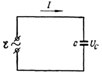
First, let's talk about capacitive resistance in more detail. Suppose a capacitor of capacitance C is connected to a sinusoidal alternating current source, then the EMF of this source will be described by the following formula:
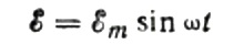
We will ignore the voltage drop across the connecting wires, as it is usually very small and can be considered separately if necessary. Let us now assume that the voltage across the capacitor plates is equal to the AC source voltage. Then:
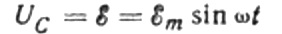
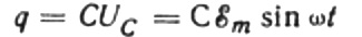
At any given moment, the charge on a capacitor depends on its capacitance and the voltage between its plates. Then, given the known source that was mentioned above, we obtain an expression for finding the charge on the capacitor plates by the source voltage:
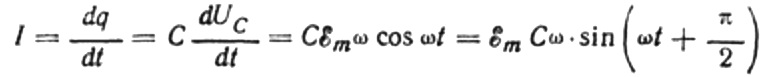
Let for an infinitesimal time dt the charge on the capacitor changes by dq, then a current I will flow through the wires from the source to the capacitor equal to:
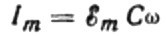
The value of the current amplitude will be equal to:
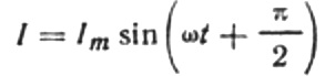
Then the final expression for the current will be:
Let's rewrite the current amplitude formula as follows:
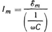
This ratio is Ohm's law, where the reciprocal of the product of angular frequency and capacitance plays the role of resistance, and is actually an expression for finding the capacitance of a capacitor in a sinusoidal alternating current circuit:
This means that the capacitive resistance is inversely proportional to the angular frequency of the current and the capacitance of the capacitor. It is easy to understand the physical meaning of this dependence.
The larger the capacitance of the capacitor in the AC circuit and the more often the direction of the current in that circuit changes, ultimately more total charge passes per unit time through the cross section of the wires connecting the capacitor to the AC source. This means that the current is proportional to the product of the capacitance and the angular frequency.
For example, let's calculate the capacitance of a capacitor with an electrical capacity of 10 microfarads for a sinusoidal alternating current circuit with a frequency of 50 Hz:

If the frequency was 5000 Hz, then the same capacitor would present a resistance of about 3 ohms.
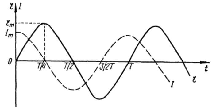
From the above formulas it is clear that the current and voltage in an AC circuit with a capacitor always change in different phases. The current phase leads the voltage phase by pi / 2 (90 degrees). This means that the maximum current in time always exists a quarter period earlier than the maximum voltage. Thus, across the capacitive resistance, the current leads the voltage by a quarter of the time period, or by 90 degrees in phase.
Let us explain the physical meaning of this phenomenon.At the first instant of time, the capacitor is completely discharged, so the slightest voltage applied to it already moves the charges on the plates of the capacitor, creating a current.
As the capacitor charges, the voltage across its plates increases, this prevents further flow of charge, so the current in the circuit decreases despite further increases in the voltage applied to the plates.
This means that if at the initial moment of time the current was maximum, then when the voltage reaches its maximum after a quarter period, the current will stop completely.
At the beginning of the period, the current is maximum and the voltage is minimum and starts to increase, but after a quarter of the period, the voltage reaches a maximum, but the current has already dropped to zero by this time. Thus it turns out that the voltage leads the voltage by a quarter of the period.
AC inductive resistance
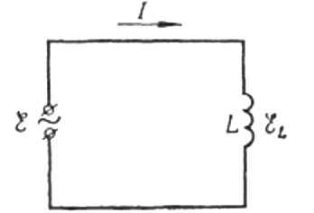
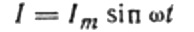
Now back to inductive resistance. Assume that an alternating sinusoidal current flows through a coil of inductance. It can be expressed as:
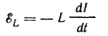
The current is due to the alternating voltage applied to the coil. This means that an EMF of self-induction will appear on the coil, which is expressed as follows:
Again, we neglect the voltage drop across the wires connecting the EMF source to the coil. Their ohmic resistance is very low.
Let the alternating voltage applied to the coil at any instant of time be completely balanced by the arising EMF of self-induction equal to it in magnitude but opposite in direction:
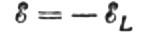
Then we have the right to write:
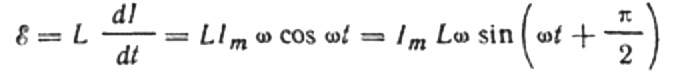
Since the amplitude of the voltage applied to the coil is:
we get:

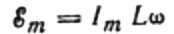
Let us express the maximum current as follows:
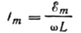
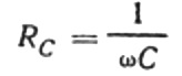
This expression is essentially Ohm's law. A quantity equal to the product of the inductance and the angular frequency plays the role of resistance here and is nothing more than the inductive resistance of the inductor:
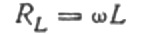
So, the inductive resistance is proportional to the inductance of the coil and the angular frequency of the alternating current through that coil.
This is due to the fact that inductive resistance is due to the influence of self-induction EMF on the source voltage, - self-induction EMF tends to reduce the current and therefore brings resistance in the circuit. The magnitude of the emf of self-induction, as is known, is proportional to the inductance of the coil and the rate of change of the current through it.
For example, let's calculate the inductive resistance of a coil with an inductance of 1 H, which is included in a circuit with a current frequency of 50 Hz:

If the frequency of the ball was 5000 Hz, then the resistance of the same coil would be approximately 31,400 ohms. Recall that the ohmic resistance of the coil wire is usually a few ohms.
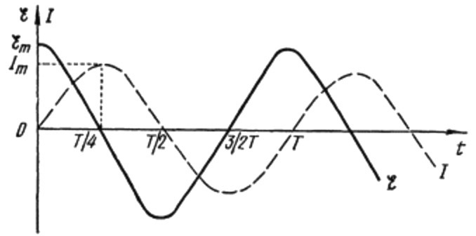
From the above formulas, it is obvious that the changes in the current through the coil and the voltage in it occur in different phases, and the phase of the current is always less than the phase of the voltage at pi / 2. Therefore, the maximum current occurs a quarter period later than onset of maximum stress.
In inductive resistance, the current lags the voltage by 90 degrees due to the braking effect of the self-induced EMF, which prevents the current from changing (both increasing and decreasing), so the maximum current is observed in the circuit with the coil later than the maximum voltage.
Coil and capacitor combined action
If you connect a coil with a capacitor in series with an alternating current circuit, then the coil voltage will advance the capacitor voltage in time by half a period, that is, by 180 degrees in phase.
Capacitive and inductive resistance are called reactants… Energy is not expended in reactive resistance as in active resistance. The energy stored in the capacitor is periodically returned back to the source when the electric field in the capacitor disappears.
It is the same with a coil: as the coil's magnetic field is created by the current, the energy in it accumulates during one quarter of the period, and during the next quarter of the period it returns to the source. In this article, we have talked about sinusoidal alternating current, for which these regulations are strictly followed.
In AC sinusoidal circuits, cored inductors are called suffocatingare traditionally used for current limiting. Their advantage over rheostats is that energy is not dissipated in huge amounts as heat.