The principle and methods of indirect determination of the power factor in the alternating current circuit
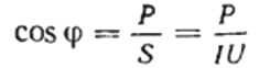
Power factor or cosine phi, with respect to the user of sinusoidal alternating current, is the ratio of the active power consumption P to the total power S that is supplied to this user from the network.
Total power S, in the general case, can be defined as the product of the effective (root mean square) values of the current I and the voltage U in the considered circuit, and the active power P — as irreversibly consumed by the user for the operation of work.
Reactive power Q, although it is part of the total power, however, it is not consumed to perform work, but only participates in the creation of alternating electric and magnetic fields in some elements of the user's circuit.
except direct power factor measurement use of electrodynamic devices — phase meters, there are quite logical indirect methods that allow you to mathematically accurately understand the value of this very important electrical quantity that characterizes the user in a sinusoidal alternating current circuit.
Let's look at the data indirect methods in details, Let us understand the principle of indirect power factor measurement.
Voltmeter, ammeter and wattmeter method
Electrodynamic wattmeter with additional active resistance in the circuit of its moving coil indicates the value of extremely active power consumed in the AC circuit P.
If now, using a voltmeter and an ammeter, we measure the average values of the current I and the voltage U acting in the circuit of the load under study, then by multiplying these two parameters, we will get only the total power S.
Then the power factor (cosine phi) of a given load can be easily found using the formula:
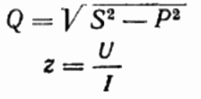
Here, if you wish, you can also find the value of the reactive power Q, the total resistance of the circuit z Ohm's Law, as well as active and reactive resistance, simply by constructing or representing a resistance triangle, and then using the Pythagorean theorem:
Counter and ammeter method
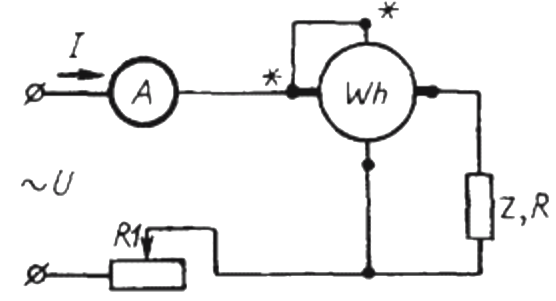
To use this method, it is necessary to assemble a circuit in which the simplest is connected in series with the load Z and the ammeter electricity meter Wh.
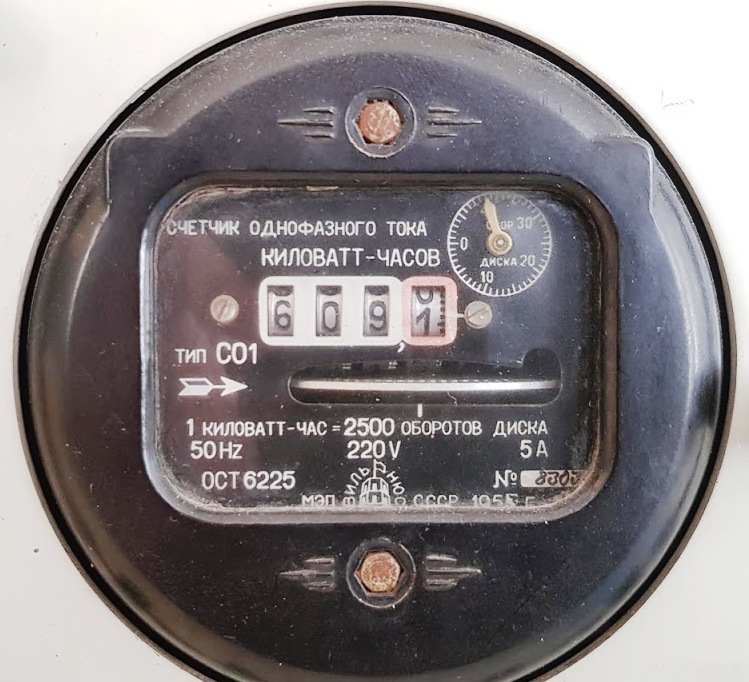
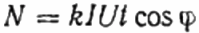
For a certain period of time t, of the order of a minute, it will be necessary to calculate the number of revolutions of the disk N, which will show the amount of active energy spent during a given time (ie, taking into account the power factor).
Here: the number of revolutions of the disk N, the coefficient k is the amount of energy per revolution, I and U are the rms current and voltage respectively, t is the time for counting the revolutions, cosine phi is the power factor:
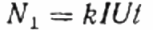
Then, instead of the studied user Z, the active load R is included in the circuit through the same counter, but not directly, but through the rheostat R1 (achieving the same current I as in the first case, with the user Z). The number of revolutions of the disk N1 is maintained for the same time t. But here, since the load is active, the cosine phi (power factor) is certainly equal to 1. Hence:
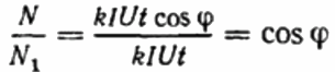
Then the ratio of revolutions of the disk counter is recorded for the same period of time in the first and second cases. This will be cosine phi, that is, the power factor of the first load (relative to a purely active load with the same current):
Three ammeter method
To determine the power factor in a sinusoidal current circuit using three ammeters, you must first assemble the following circuit:
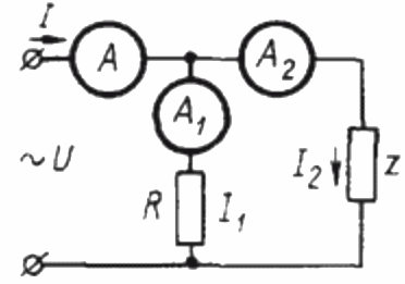
Here Z is a load whose power factor is to be determined and R is a purely active load.
Since the load R is purely active, the current I1 at any instant of time is in phase with the alternating voltage U applied to this load. In this case, the current I is equal to the geometric sum of the currents I1 and I2. Now we will build based on this position a vector diagram of the currents:
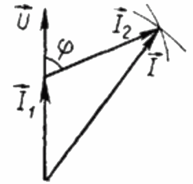
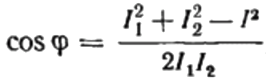
On the vector diagram of the currents, the acute angle between the current I1 and the current I2 is the angle phi, the cosine of which (in fact, the value of the power factor) can be found from a special table of values of trigonometric functions or calculated by the formula:

From here we can express cosine phi, that is, the desired power factor:
The sign of the power factor found («+» or «-«) will indicate the nature of the load. If the power factor (cosine phi) is negative, the load is capacitive in nature. If the power factor is a positive value, then the nature of the load is inductive.