Asynchronous motor operation
Operation of the induction motor is graphically expressed dependences of speed n2, efficiency η, useful torque (shaft torque) M2, power factor cos φ and stator current I1 on useful power P2 at U1 = const f1 = const.
Velocity characteristic n2 = f (P2). The rotor speed of the induction motor n2 = n1 (1 — s).
Slide s = Pe2 / Rem, i.e. the slip of the induction motor and therefore its speed is determined by the ratio of electrical losses in the rotor to electromagnetic power. Neglecting electrical losses in the rotor at idle, we can take Pe2 = 0 and therefore s ≈ 0 and n20 ≈ n1.
As the shaft load increases asynchronous engine the ratio s = Pe2 / Pem increases, reaching values of 0.01 — 0.08 at nominal load. Accordingly, the dependence n2 = f (P2) is a curve slightly inclined to the abscissa axis. However, as the motor rotor active resistance r2 ' increases, the slope of this curve increases. In this case, changes in the frequency of the induction motor n2 with fluctuations in the load P2 increase.This is explained by the fact that as r2 ' increases, the electrical losses in the rotor increase.
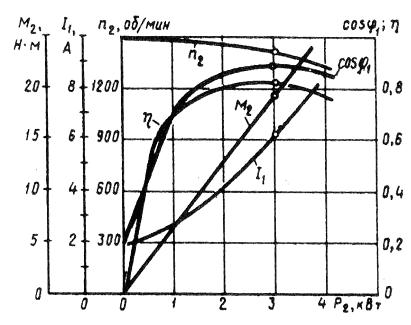
Rice. 1. Characteristics of operation of the induction motor
Dependence M2 = f (P2). The dependence of the useful torque from the shaft of the asynchronous motor M2 on the useful power P2 is determined by the expression M2 = P2 / ω2 = 60 P2 / (2πn2) = 9.55P2 / n2,
where P2 — useful power, W; ω2 = 2πf 2/60 is the angular frequency of rotation of the rotor.
It follows from this expression that if n2 = const, then the graph M2 = f2 (P2) is a straight line. But in an induction motor with an increase in the load P2, the speed of the rotor decreases and therefore the useful moment of the shaft M2 with an increase in the load increases a little faster than the load and therefore the graph M2 = f (P2 ) has a curvilinear shape.
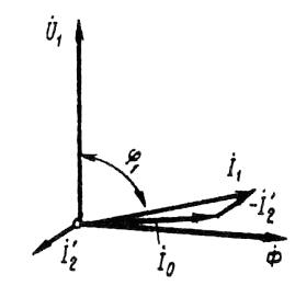 Rice. 2. Vector diagram of an induction motor at low load
Dependence cos φ1 = f (P2). Due to the fact that the stator current of the induction motor I1 has a reactive (inductive) component necessary to create a magnetic field in the stator, the power factor of induction motors is less than unity. The lowest value of the power factor corresponds to idling. This is explained by the fact that the idle current of the electric motor I0 at any load remains practically unchanged. Therefore, at low motor loads, the stator current is small and largely reactive (I1 ≈ I0). As a result, the phase shift of the stator current with respect to the voltage is significant (φ1 ≈ φ0), only slightly less than 90 ° (Fig. 2).
The no-load power factor of induction motors is usually less than 0.2.As the load on the motor shaft increases, the active component of the current I1 increases and the power factor increases, reaching the highest value (0.80 — 0.90) at a load close to the nominal one. A further increase in the load on the motor shaft is accompanied by a decrease in cos φ1, which is explained by an increase in the inductive resistance of the rotor (x2s) due to an increase in the slip and, therefore, in the frequency of the current in the rotor.
In order to improve the power factor of induction motors, it is extremely important that the motor always runs, or at least a significant part of the time, with a load close to the rated load. This can only be achieved with the correct choice of engine power. If the motor runs under load for a significant part of the time, then to increase cos φ1 it is advisable to decrease the voltage U1 supplied to the motor. For example, in motors operating when the stator winding is delta connected, this can be done by reconnecting the stator windings in star, which will cause the phase voltage to decrease by a factor. In this case, the stator magnetic flux, and hence the magnetizing current, decreases by about a factor. In addition, the active component of the stator current increases slightly. All this contributes to increasing the power factor of the engine.
In fig. 3 shows the graphs of the dependence of cos φ1, asynchronous motor on the load, when the stator windings are connected in star (curve 1) and delta (curve 2).

Rice. 3. Dependence of cos φ1 on the load when connecting the stator winding of the motor with star (1) and delta (2)