Thyristor starters
 Thyristor starters are contactless devices and are used to switch electromechanical systems on and off. In each phase of the starter (Fig. 1), without blocking thyristors VS1 — VS3 and diodes VD1 — VD3.
Thyristors are opened once per period consecutively at time intervals T / 3, at the moments of time when a pulse is applied to open the thyristor, when the voltage passes through zero in the direction of its increase in the direction of conduction.
After the voltage reaches zero, the thyristor becomes non-conductive and the voltage of that phase is fed through the parallel diode. After a third of the period, the next thyristor turns on, and so on. This provides a continuous supply of energy to the receiver, for example the MA induction motor (Fig. 1). Note that there are no contact devices in the device, there are only «Start» and «Stop» buttons.
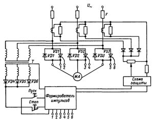
Rice. 1. Thyristor starter
Pulses for opening the thyristors are supplied to terminals 1, 2, 3, 4, 5, 6 of the shaping pulse, which is fed by a separate transformer T through diodes VD4, VD5 and VD6, which ensures the supply of the same polarity pulses.When the «Start» button is pressed, the pulse shaper and the starter are switched on.
Motor protection is provided by fuses F and an overcurrent protection circuit. Current transformers are included in each phase of the starter. The currents of the three phases are summed and converted to voltage. When the voltage is set, if it does not act for a short time, the opening impulses are removed and the drive stops. Pressing the Stop button also stops the pulses.
Thyristor starter pulse generator
To control thyristors, that is, to form control pulses at appropriate times, various devices can be used: electromagnetic devices with magnetic amplifiers and transformers, low-power thyristor devices, transistor devices, etc. The most common are transistor circuits, one of which will be considered.
Management can be done horizontally or vertically. In horizontal control, the AC voltage can be phase-shifted ('horizontal') by a phase shifter, usually between 0 and π.
Voltages derived from phase switches, for example for three-phase bridge rectifier six voltages phase-shifted by angles π / 3 are applied to the driver, which produces control pulses of sufficient duration.
More common is the vertical control principle, in which the control pulse is formed, for example, at the moments of equality of the control voltage with a linearly increasing saw voltage.
A similar circuit for a single control channel of a full-wave rectifier is shown in Fig. 2, a. The input receives a shaped alternating voltage in the form of rectangular pulseswith width π (Fig. 2, b).
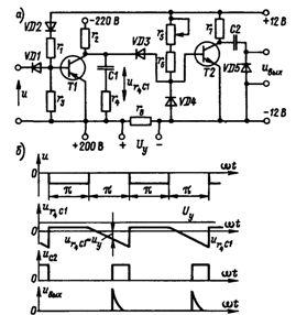
Rice. 2. Thyristor starter pulse generator: a — circuit for receiving control pulses, b — time diagrams of the voltages in the nodes of the circuit
A negative voltage is supplied through the diode VD1 to the base of the transistor VT1 during the conducting part of the period. During these time intervals, the ur4C1 voltage is relatively low. After the negative voltage is removed from the base of the transistor VT1, the voltage ur4C1 begins to increase almost linearly at large resistances r2 and r4.
When this increasing stress ur4C1 will become equal to the control voltage Uy, the voltage appears at the output of the transistor VT2. When differentiating the current pulse in the circuit of the transistor VT2, a voltage pulse is formed in the thyristor control circuit.
In the presented diagram (Fig. 2, a), the diode VD4 serves to limit the negative voltage supplied to the base of the transistor VT2, the diode VD3 prevents the closing of the control voltage source through the discharged capacitor C1 or the saturated transistor VT1, and the diode VD5 limits the value of the output pulse.