Electrical filters — definition, classification, characteristics, main types
Industrial energy sources provide practical sinusoidal voltage curves… At the same time, in a number of cases, alternating currents and voltages, which are periodic, differ sharply from harmonic ones.
Electrical filters can be used to smooth voltage waves in rectifiers, demodulators that convert amplitude-modulated high-frequency oscillations into relatively slow changes in signal voltage, and other similar devices.
In the simplest case, you can limit yourself to serial connection with the load inductors, whose resistance increases with increasing harmonic order and is relatively small for low-frequency oscillations and even more so for the constant component. It is more effective to use U-shaped, T-shaped and L-shaped filters.
Basic definitions and classification of electrical filters
The selectivity of the filter is its ability to select a certain range of frequencies inherent in the useful signal from the entire frequency spectrum of currents entering its input.
To obtain good selectivity, the filter must pass currents at frequencies inherent to the desired signal with minimum attenuation and have maximum attenuation for currents at all other frequencies. In accordance with this filter, the following definition can be given.
An electrical filter is called a four-pole device that transmits currents in a certain frequency band with little attenuation (bandwidth), and currents with frequencies outside this band — with high attenuation or, as it is usually said, does not pass (non-transmission band).
According to the structure of the circuits, filters are divided into chain (column) and bridge filters. Chain filters are filters made according to T-, P- and L-shaped bridge circuits. Bridge filters are filters made on a bridge circuit.
Depending on the nature of the elements, filters are divided into:
-
LC — elements of which are inductance and capacitance;
-
RC — elements of which are active resistances and capacities;
-
resonator — the elements of which are resonators.
According to the presence of energy sources in the filter circuit, they are divided into:
-
passive — not containing energy sources in the circuit;
-
active — containing energy sources in the circuit in the form of a lamp or crystal amplifier; sometimes called active element filters.
For a complete characterization of filter performance, it is necessary to know its electrical characteristics, which include the frequency dependences of attenuation, phase shift, and characteristic impedance.
The best is a filter that, with a minimum number of elements, has:
-
the maximum steepness of the damping characteristic;
-
high attenuation in the non-transmit band;
-
minimal and constant attenuation in the passband;
-
maximum constancy of the characteristic impedance in the passband;
-
linear phase response;
-
the possibility of easy and smooth adjustment of the frequency band and its width;
-
constancy of characteristics that do not depend on: voltages (currents) acting at the filter input, temperature and humidity of the environment, as well as the influence of external electrical and magnetic disturbances;
-
ability to work in different frequency ranges;
-
the size, weight and cost of the filter must be kept to a minimum.
Unfortunately, there is no single elementary type of filter whose characteristics meet all these requirements. Therefore, depending on the specific conditions, such types of filters are used, the characteristics of which best meet the technical requirements. Very often it is necessary to apply filters to complex circuits consisting of elementary connections of various types.
The most common types of filters
In fig. 1 shows the diagram of a simple L-shaped filter with inductor L and capacitor C connected between receiver rpr and rectifier V.
The alternating currents at all frequencies meet a significant inductor resistance, and a parallel-connected capacitor passes the residual high-frequency currents along the parallel branch. This significantly reduces voltage ripples in the load. rNS.
Filters consisting of two or more similar links can also be used. Sometimes simple filters with resistors are used instead of inductors.
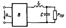
Rice. 1.The simplest smoothing L-shaped electric filter
More advanced are the resonant filters they use resonance phenomena.
When the inductor and capacitor are connected in series, when fwL = 1 / (kwV), the circuit will have the highest conductivity (active) at the frequency fw and quite high conductivities in the frequency band close to the resonance. This circuit is a simple bandpass filter.
When the inductor and capacitor are connected in parallel, such a circuit will have the lowest conductivity at the resonant frequency and relatively low conductivity in the frequency band close to the resonant frequency. Such a filter is a blocking filter for a certain frequency band.
To improve the performance of a simple band-pass filter, it is possible to use a scheme (Fig. 2) in which an inductor and a capacitor are connected in parallel to each other in parallel to the receiver. Such a circuit is also tuned in resonance with the frequency of the goats and presents a very high resistance for currents in the selected frequency band and much less resistance for currents of other frequencies.
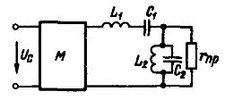
Rice. 2. Schematic of a simple bandpass filter
A similar filter can be used in modulators that produce modulated oscillations at a specific frequency. A low-frequency signal voltage Uc is applied to the modulator M, which is converted into modulated high-frequency oscillations, and the filter separates the voltage from the required frequency, which is fed to the load rNS.
Suppose, for example, that a non-sinusoidal alternating current flows through the circuit and that very large third and fifth harmonic currents are to be eliminated from the receiver current curve.Next, we will alternately include two circuits tuned to resonance for the third and fifth harmonics in the circuit (Fig. 3, a).
A left line impedance tuned to resonance for a frequency of 3w will be very large for that frequency and small for all other harmonics; a similar role is played by the right circuit tuned to resonance for frequency 5w... Therefore, the current curve of the input receiver will almost not contain the third and fifth harmonics (Fig. 3, b), which will be suppressed by the filter.
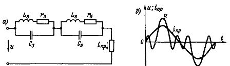
Rice. 3. Scheme with series-connected resonant circuits tuned to resonance for the third and fifth harmonics: a — circuit diagram; b — curves of voltage and circuit and current inp of the receiver
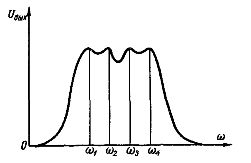
Rice. 4. Bandpass filter output voltage curve
In some cases, more sophisticated band-pass filters are performed, as well as cut-off filters that pass or do not pass oscillations starting at a certain frequency. Such filters consist of T-shaped or U-shaped connections.
The principle of operation of filters is that in the frequency band of frequencies, for example, a bandpass filter, resonance occurs at n + 1 frequencies, where n is the number of connections. A curve Uout = f (w) for such a filter composed of three connections is shown in Fig. 4. Resonance occurs at frequencies w1,w2, w3 and w4.
See also on this topic: Power filters andInput and output filters for frequency converters