Dynamic engine braking circuit
 Some technologies require the braking process of the electric drive to take place more intensively than under the influence of static torque alone. In this case, different types of electrical braking are used in the control circuits — dynamic braking and opposite braking, as well as mechanical braking using electromagnetic brakes. The most popular and common way is to use dynamic engine braking.
The figure shows a schematic diagram of an irreversible electric drive that allows starting and stopping an electric motor with dynamic braking.
The circuit is powered by an automatic switch QF, alternating current voltage to the stator winding is supplied by linear contactor KM1, and direct current voltage is supplied by KM2 dynamic brake contactor (starter). The source of direct current contains a transformer T and a rectifier V1, which are connected to the mains through the contactor KM2 only in the stop mode.
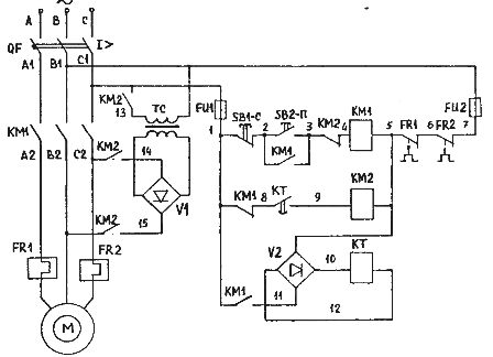
Schematic of an irreversible asynchronous electric drive with dynamic braking
The start command is given by the SB2-P button and the stop command is given by the SBC button. When pressed, contactor KM1 turns on and the motor is connected to the mains. To stop the engine, press the SB1-C button, contactor KM1 turns off and disconnects the engine from the mains. At the same time, the normally closed (NC) block contact KM1 turns on the contactor KM2, which supplies direct current to the motor stator windings. The engine goes into dynamic braking mode. The duration of the DC supply to the stator windings is controlled by the time relay KT. After turning off the coil KT, its contact in the circuit of the coil KT2 opens.
The circuit uses zero, maximum current carried by line contactor KM1, QF breaker with overcurrent release, respectively. The control circuit is protected by fuses FU1 and FU2. When one of the protections is triggered, the KM1 line contactor is tripped. The interlock used in the chain of contacts 3-4 and 1-8 prohibits the simultaneous operation of contactors KM1 and KM2.
Thermal protection of the motor is carried out by thermal relays FR1, FR2, the breaking contacts of which are included in the coil circuit of the contactor KM. When one of the thermal relays is tripped, the KM contactor opens and the circuit returns to its original state. It can be turned on again after the thermal relay and the motor have cooled down.