Two-speed motor control circuit
 In various metal cutting machines, mechanisms and technological installations, electric drives with two-speed asynchronous electric motors are used, in which step control of the speed is achieved by changing the number of pole pairs by changing the switching circuit of a specially made stator winding.
The figure shows a diagram of an irreversible electric drive two-speed asynchronous motor… The circuit provides for switching the stator winding from a delta to a double star (Δ / YY). Such a scheme is used in electric drives of mechanisms, if the technology requires speed control with a constant power of the working body.
Circuit targeting commands are given by the three-position SM controller. In the initial position, when machines QF1 and QF2 are switched on and the controller is in the zero (left) position, the KV voltage relay is energized and its KV contact is self-energized.
When the controller is switched to the first position (HC), the coil of the contactor KM1 (HC) receives power, the contactor operates, closes its contact 3-6 in the circuit of the coil of the brake contactor KMT and connects the stator winding in the delta (Δ) to the network . At the same time, the brake contactor KMT is activated and energizes the brake solenoid, the brake is released (the pads are lifted) and the electric motor is started at low speed (the number of poles is 2p).
When the regulator is switched to the second position (BC), the contactor winding KMl (HC) disconnects the stator winding from the mains. The coils of contactors KM2 (BC) and KM3 (BC) are energized and the contactors are activated. Contactor KM3 (BC), closing its contacts, forms the zero point of a double star. Contactor KM2 (BC) closes its contact 3-6 in the coil circuit of the brake contactor KMT, the contactor KMT operates or remains on. At the same time, the contactor KM2 (BC) connects the upper part of the double star of the stator winding, and the motor starts at high speed (the number of poles p).
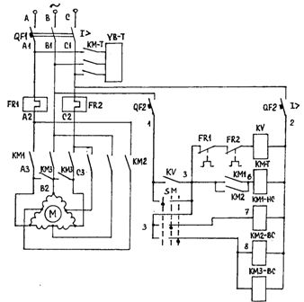
Circuit diagram of a two-speed induction motor
To stop the electric drive, it is necessary to switch the controller to the zero position. In this case, the contactors lose power, the stator winding is disconnected from the network and the KMT contacts are open. The KMT contactor removes power from the electromagnetic brake coil and the brake pads are applied to the brake drum. The electric drive stops under the action of the resistance moment Mc and the moment Mmt of the mechanical brake.