Schematic of an asynchronous electric drive with opposition braking
 When, according to the conditions of the technological process, it is necessary to significantly accelerate the braking process of the electric motor, then reverse braking is used. A diagram of a reversible asynchronous electric drive in which opposite braking is implemented is shown in Fig. 1. Based on the operating conditions of the electric drive, the control circuit is fed by a reduced standard voltage from the TC transformer.
The circuit allows direct start, reverse and stop of the electric drive by means of a counter-switching brake with speed control. In this case electromechanical speed control relay SR mounted on motor shaft. It closes its SR (B) or SR (H) contacts with speed

Control commands are sent to the circuit control buttons SB2 ("Forward"), SVZ ("Reverse") and SB1 ("Stop") depending on the direction of rotation required by the technology. The voltage to the stator winding is supplied by contactors KM1 (B), phase sequence ABC and KM2 (H), phase sequence CBA.
The stop button of the electric drive SB1 (C) is included in the coil circuit of the brake relay KT, which organizes the anti-rotation braking mode in any direction of rotation. In the coil circuits of contactors KM1 (B) and KM2 (N) there are blocking contacts 5-6 (SB3), 6-7 (KM2) and 12-13 (SB2) 13-14 (KM1), preventing the simultaneous operation of these contactors.
The electric drive is managed as follows. When the SB2-B button is pressed, the supply circuit of the coil KM1 is formed, the contactor KM1 is activated and connects the stator winding of the asynchronous electric motor to the supply network, and a direct start is obtained.
When the KM1-B contactor is actuated, contact 4-5 (KM1-B) closes, bypassing the SB2-B button, and the contactor is self-energized. At the same time, the blocking contact 13-14 (KM-B) opens in the circuit of the coil KM2-N, and the contact 3-15 (KM1-B) closes in the circuit of the coil of the brake relay KT. When the motor accelerates, the speed control relay activates and closes its contact 11-13 (SR-H), preparing the circuit to stop the drive if the SBl-C (Stop) button is pressed.
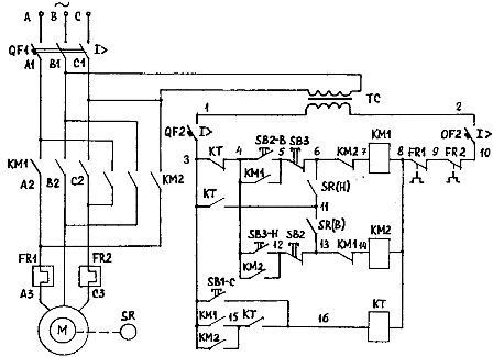
Rice. 1. Scheme of reversible asynchronous electric drive with opposition braking
To reverse the electric drive, press the SB3-H button. Then the blocking contact 5-6 (SB3) opens in the circuit of the coil KM1. Contactor KM1 disconnects the motor stator from the mains. At the same time, the blocking contact 13-14 (KM1) closes in the circuit of the coil KM2.
The KM2 winding receives power, and the KM2 contactor connects the stator winding to the mains, changing the phase sequence.The magnetic field of the electric motor begins to rotate in the opposite direction, and the rotor by inertia rotates in the same direction. Therefore, the induction motor goes into stop-against-rotation mode until it comes to a complete stop, and then accelerates in the «Reverse» direction.
During reverse acceleration, the speed control relay closes its contact 11-6 (SR-B), preparing the circuit to stop. In the coil circuit of the brake relay KT, the contactor closes 3-15 (KM2).
When the SB1-C button is pressed, the CT brake relay coil is energized and the CT relay is energized, opening contact 3-4 (CT) and closing contact 3-11 (CT). Contactor KM2 loses power and disconnects the stator winding from the mains. In this case, contactor KM2 closes its blocking contact 6-7 (KM2) in the circuit of winding KM1.
Contactor KM1 is activated because coil KM 1-B receives power through circuit 3-1 (KT), 11-6 (SR-H), 6-7 (KM2). The stator winding is connected by direct phase rotation, «forward», and the rotor rotates by inertia in the «back» direction. Therefore, the induction motor goes into the opposite braking mode. Braking torque of the electric drive in braking mode

When the speed drops to near zero, the SR speed control relay will open its contact 3-11 (KT) and the KMl coil will lose power and the KM1 contactor will de-energize the stator winding.