How to correctly calculate the current when choosing the cross section of wires and cables
Construction of the computational scheme of the network
To select the cross-sections of individual sections of the electrical network, but the heating conditions and the economic current density, it is enough to know only the current loads of these sections of the network. Calculation of the network for voltage loss can only be carried out if not only the loads but also the lengths of all sections of the network are known. In this regard, when you start calculating the network, it is necessary first of all to prepare its calculation scheme, which should indicate the loads and lengths of all sections.
When calculating three-phase networks, the loads on all three phase conductors are assumed to be the same. In fact, this condition is strictly fulfilled only for electric networks with three-phase electric motors. For networks with single-phase energy consumers, for example, urban networks with lighting lamps and household appliances, there is always some uneven distribution of the load on the phases of the line.In practical calculations of networks with single-phase receivers, the distribution of loads in phases is also assumed conditionally uniform.
Provided that the phases of the line are uniformly loaded, there is no need to indicate all the conductors of the network in the design scheme. It is enough to imagine one line diagram indicating all loads connected to the network and the lengths of all network sections. The diagram should also indicate the installation locations. fuses or other protective devices.
When drawing up the design scheme of the electrical wiring in the room, you should use the plans and sections of the building on which the electrical wiring should be applied, indicating the connection points of the electrical receivers.
The design scheme of the external network is prepared according to the plan of the village or industrial enterprise, on which the network should also be applied, and the connection points of groups of energy consumers (houses or individual buildings of an industrial enterprise) are indicated.
The lengths of all sections of the network are measured according to the drawing, taking into account the scale in which it is drawn. In the absence of a drawing, the lengths of all sections of the network must be measured in kind.
When drawing up the calculation scheme of the network, compliance with the scale for the network sections is not required. It is only necessary to observe the correct sequence of connecting the individual sections of the network to each other.
The figure shows an example of a design scheme of the line of the external network of the village.The lengths of the network sections in the diagram are indicated above and to the left in meters, below and to the right of the load are represented by arrows that show the calculated power in kilowatts. The line ABC is called backbone, the sections DB, BE and VG are called branches.
As can be seen from the figure, individual sections of the network are presented without a scale, which does not interfere with the accuracy of the calculation if the length of the sections is specified correctly.
 Calculation scheme of a section of the external network 380/220 V of a residential area.
Determination of the calculated loads of the electrical network
Determining design loads (powers) is a much more difficult task. A lighting lamp, heating device or television at rated terminal voltage consumes a certain rated power, which can be taken as the rated power of this receiver. The situation is more complicated with an electric motor, for which the power consumed by the network depends on the torque of the mechanism connected to the motor - machine tool, fan, conveyor, etc.
On plate attached to the motor housing, its rated power is indicated. The actual power consumed by the motor from the network differs from the nominal one. For example, the load on the lathe motor will vary depending on the size of the part, the thickness of the chips being removed, etc.
The engine is selected for the most difficult operating conditions of the machine and therefore in other operating modes the engine will be underloaded… Thus, the rated power of the motor is usually less than its rated power.
Determining the calculated power for a group of electrical receivers becomes even more complicated, since in this case it is necessary to take into account the possible number of connected receivers.
Imagine that you need to determine the estimated load for a line that supplies a workshop with 30 electric motors. Of these, only a few will run continuously (eg motors connected to fans).
The machine engines run intermittently while installing a new machining part. Some of the motors may run at part load or idle, etc. In this case, the load on the service line will not remain constant. It is clear that the maximum possible load should be taken as the calculated load of the line, as the heaviest for the conductors of the line.
The highest load is understood not as its short-term impulse, but as the largest average value over a half-hour time period.
The design load (kW) of a group of electrical receivers can be determined by the formula

where Ks — demand factor for the highest load mode, taking into account the largest possible number of allowed receivers in the group. For motors, the slope factor must also take into account the size of their load;
Ru is the installed power of a group of receivers, equal to the sum of their nominal powers, kW. You can always familiarize yourself in more detail with the methods for determining project loads in the specialized literature.
Determination of the estimated line current for one consumer of electrical energy and a group of electrical consumers
When choosing the cross-section of the wires according to the heating conditions or according to the economic current density, it is necessary to determine the value of the calculated line current. For a three-phase electric consumer, the value of the nominal current (A) is determined by the formula
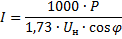
where P is the estimated power of the receiver, kW; Un-nominal voltage at the terminals of the receiver, equal to the phase (phase) voltage of the network to which it is connected, V; cos f — Power factor receiver.
This formula can also be used to determine the rated current of a group of three-phase or single-phase receivers, provided that the single-phase receivers are connected equally to all three phases of the line. The value of the calculated current (A) for a single-phase receiver or for a group of receivers connected to one phase of a three-phase current network is determined by the formula

where U n.f — the nominal voltage of the receivers, equal to the phase voltage of the network to which they are connected, V.
The value of the calculated current for a group of receivers connected to a single-phase current line is also determined by this formula.
For incandescent lamps and heating devices, the power factor cosphi = 1. In this case, the formulas for determining the calculated current are simplified accordingly.
Determination of current according to the design scheme of the electrical network
Let's go back to the design scheme of the external network of the residential settlement shown in the figure. In this diagram, the design loads of the houses connected to the line are indicated in kilowatts at the ends of the corresponding arrows. To choose the cross-section of linear wires, you need to know the load on all sections.
This load is determined based on Kirchhoff's first law, according to which for each point of the network the sum of the incoming currents must be equal to the sum of the outgoing currents. This law is also valid for loads expressed in kilowatts.
Let's find the distribution of loads on the sections of the line. At the end of the line, on a section 80 m long, adjacent to point G, the load of 9 kW is equal to the calculated load of the house connected to the line at point G. On the branched section 40 m long, adjacent to point B, the load is equal to the sum of the loads of the houses connected to the section VG branch: 9 + 6 = 15 kW. On a 50 m long section of highway adjacent to point B, the load is 15 + 4 + 5 = 24 kW.
The loads on all other sections of the line are determined in the same way. In order not to provide all the numbers indicated in the diagram with the designations of the corresponding units (m, kW), the lengths and loads on the diagram must be arranged in a certain order. In the design scheme of the figure, the lengths of the linear sections are indicated on the top and left, the loads on the same sections are indicated on the bottom and right.
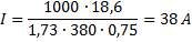
An example. A four-wire line with a nominal voltage of 380/220 V supplies a workshop with 30 electric motors, the total installed power Py1 = 48 kW. The total power of the lighting lamps in the workshop is Ru2 = 2 kW, the demand factor for the power load Kc1 = 0.35 and for the lighting load Kc2 = 0.9. Average power factor for the entire installation cos f = 0.75. Determine the calculated line current.
Answer.We determine the calculated load of electric motors: P1 = 0.35 x 48 = 16.8 kW and the calculated load of lighting P2 = 0.9 x 2 = 1.8 kW. The total design load is P = 16.8 + 1.8 = 18.6 kW.
Determine the rated current: