Automatic control circuits for starting and stopping DC motors
 The starting of any engine is accompanied by certain switches in the power circuit and the control circuit. In this case, relay-contactor and non-contact devices are used. For DC motors to limit starting currents starting resistors are included in the rotor and armature circuit of the motors, which are switched off when the motors are accelerated in steps. When startup is complete, the startup resistors are completely bypassed.
The braking process of the motors can also be automated. After the stop command, with the help of the relay-contactor equipment, the necessary switches are made in the power circuits. When approaching a speed close to zero, the motor is disconnected from the network. During startup, steps are turned off at regular intervals or depending on other parameters. This changes the current and speed of the motor.
Motor starting control is performed as a function of EMF (or speed), current, time, and path.
Typical subassemblies and circuits for automatic control of starting DC motors
Starting a DC motor with parallel or independent excitation is done with a resistor introduced in the armature circuit. A resistor is required to limit the inrush current. As the motor accelerates, the starting resistor is stepped. When the start is complete, the resistor will be completely bypassed and the motor will return to its natural mechanical characteristics (Fig. 1). At startup, the engine accelerates according to artificial characteristic 1, then 2, and after maneuvering the resistor - according to natural characteristic 3.
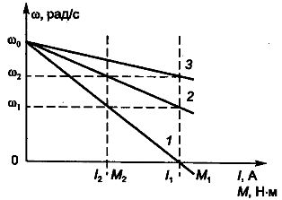
Rice. 1. Mechanical and electromechanical characteristics of a DC motor with parallel excitation (ω — angular speed of rotation; I1 M1 — peak current and torque of the motor; I2 M2 — current and switching moment)
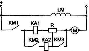
Consider the starting circuit node of the DC motor (DCM) in the EMF function (Fig. 2).
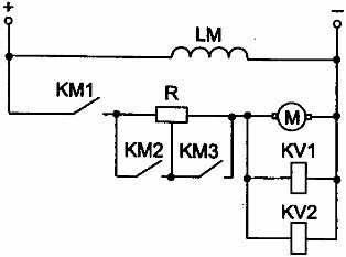
Rice. 2. The starting circuit node of DCT of parallel excitation in the EMF function
The EMF (or speed) function is controlled by relays, voltages and contactors. Voltage relays are configured to operate at different armature emf values. When the contactor KM1 is turned on, the voltage of the KV relay at the time of starting is not enough for operation. When the motor accelerates (due to the increase in motor emf), the KV1 relay is activated, then KV2 (the relay activation voltages have corresponding values); they include the acceleration contactors KM2, KMZ, and the resistors in the armature circuit are shunted (contactor switching circuits are not shown in the diagram; LM is the excitation winding).
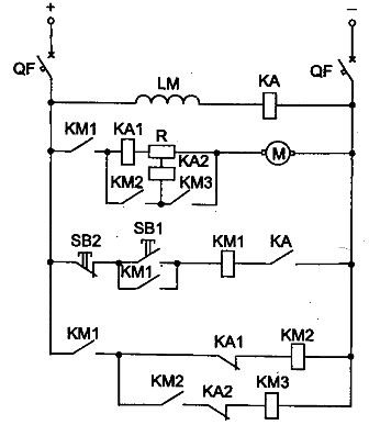
Let's look at the scheme for starting a DC motor in the EMF function (Fig. 3). The angular velocity of the motor is often fixed indirectly, i.e.measuring quantities related to speed. For a DC motor, such a value is the EMF. The start is carried out as follows. The QF circuit breaker turns on, the motor field is connected to the power supply. The KA relay activates and closes its contact.
The remaining devices of the circuit remain in their original position. To start the engine, you must press the button SB1 «Start», after which contactor KM1 is activated and connects the motor to the power source. Contactor KM1 is self-powered. The DC motor is accelerated with the motor armature circuit resistor R.
As the speed of the motor increases, its emf and the voltage in the coils of the relays KV1 and KV2 increase. At speed ω1 (see Fig. 1.) relay KV1 is activated. It closes its contact in contactor circuit KM2, which trips and short-circuits the first stage of the starting resistor with its contact. At speed ω2 relay KV2 is energized. With its contact, it closes the supply circuit of the KMZ contactor, which, when actuated, with a contact, short-circuits the second starting stage of the starting resistor. The engine reaches its natural mechanical characteristics and terminates takeoff.
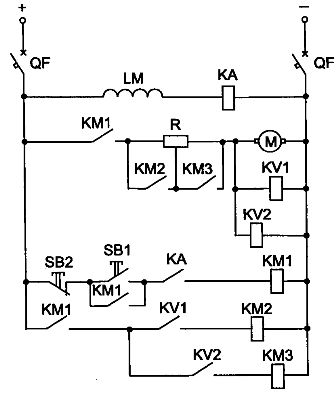
Rice. 3. Schematic of starting DCT of parallel excitation in the EMF function
For the correct operation of the circuit, it is necessary to set the voltage relay KV1 to operate at the EMF corresponding to the speed ω1 and the relay KV2 to operate at the speed ω2.
To stop the engine, press the Stop button SB2. To disconnect the electrical circuit, open the QF circuit breaker.
The current function is controlled by a current relay. Consider the dc motor starter circuit node in the flux function. In the diagram shown in fig.4, overcurrent relays are used, which pick up at the inrush current I1 and drop out at the minimum current I2 (see Fig. 1). The internal response time of the current relays must be less than the contactor response time.
Rice. 4. The starting circuit node of the parallel excitation DCT depending on the current
Motor acceleration begins with the resistor fully inserted into the armature circuit. As the engine accelerates, the current decreases, with current I2, the relay KA1 disappears and with its contact closes the supply circuit of the contactor KM2, which bypasses the first contact of the starting resistor with its contact. Similarly, the second starting stage of the resistor is short-circuited (relay KA2, contactor KMZ). The contactor power circuits are not shown in the diagram. At the end of starting the motor, the resistor in the armature circuit will be bridged.
Consider the circuit for starting a DC motor as a flux function (Fig. 5). The resistances of the resistor steps are selected so that at the moment when the motor is turned on and the steps are shunted, the current I1 in the armature circuit and the moment M1 do not exceed the permissible level.
Starting a DC motor is performed by turning on the QF circuit breaker and pressing the «Start» button SB1. In this case, contactor KM1 is activated and closes its contacts. The inrush current I1 passes through the power circuit of the motor, under the influence of which the overcurrent relay KA1 is activated. Its contact opens and contactor KM2 does not receive power.
Rice. 5. Schematic of parallel excitation DCT start-up as a function of current
When the current drops to the minimum value I2, the overcurrent relay KA1 drops and closes its contact.The contactor KM2 is activated and through its main contact shunts the first section of the starting resistor and relay KA1. When switching, the current rises to the value I1.
When the current increases again to the value of I1, the contactor KM1 does not turn on, because its coil is bypassed by the contact KM2. Under the influence of the current I1, the relay KA2 is activated and opens its contact. When in the process of acceleration the current drops again to the value of I2, the relay KA2 drops and the contactor KMZ turns on. The start is complete, the engine operates with its natural mechanical characteristics.
For the correct functioning of the circuit, it is necessary that the response time of the relay KA1 and KA2 is less than the response time of the contactors. To stop the motor, press the «Stop» button SB2 and turn off the QF circuit breaker to disconnect the circuit.
Time control is accomplished using a time relay and corresponding contactors that short-circuit the resistor stages with their contacts.
Consider the starting circuit node DC motor as a function of time (Fig. 6). The time relay KT is activated immediately when voltage appears in the control circuit through the opening contact KM1. After opening the contact KM1, the time relay KT loses its power supply and closes its contact with a time delay. Contactor KM2 after a time interval equal to the time delay of the time relay receives power, closes its contact and shunts the resistance in the armature circuit.
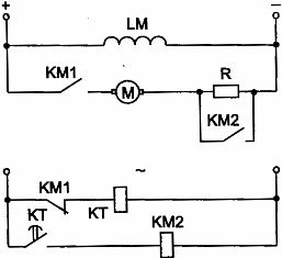
Rice. 6. The DCT starting circuit node of parallel excitation as a function of time
The advantages of control in the function of time include ease of control, stability of the acceleration and deceleration process, lack of delay of the electric drive at intermediate speeds.
Consider the circuit for starting a DC motor parallel excitation as a function of time. In fig. 7 shows a diagram of an irreversible start DC parallel excitation motor. The launch takes place in two stages. The circuit uses buttons SB1 «Start» and SB2 «Stop», contactors KM1 ... KMZ, electromagnetic time relays KT1, KT2. The QF breaker turns on. In this case, the coil of the time relay KT1 receives power and opens its contact in the circuit of the contactor KM2. The engine is started by pressing the «Start» button SB1. Contactor KM1 receives power and with its main contact connects the motor to a power source with a resistor in the armature circuit.
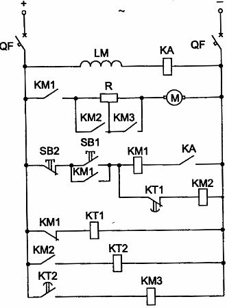
Rice. 7. Schematic of irreversible starting of a DC motor as a function of time
The undercurrent relay KA serves to protect the motor from interruption of the excitation circuit. During normal operation, the KA relay energizes and its contact in the KM1 contactor circuit closes, preparing the KM1 contactor for operation. When the excitation circuit is broken, the KA relay turns off, opens its contact, then the KM1 contactor turns off and the engine stops. When the contactor KM1 is actuated, its blocking contact closes and the contact KM1 in the relay circuit KT1 opens, which turns off and closes its contact with a time delay.
After a time interval equal to the time delay of the relay KT1, the supply circuit of the accelerating contactor KM2 is closed, which is triggered and with its main contact short-circuits one stage of the starting resistor. At the same time, the time relay KT2 is energized. The engine accelerates. After a time interval equal to the delay of the KT2 relay, the KT2 contact closes, the KMZ acceleration contactor is activated and with its main contact contacts the second stage of the starting resistor in the armature circuit. The start is complete and the engine returns to its natural mechanical characteristics.
Typical DC brake control circuit units
DC motor automatic control systems use dynamic braking, opposite braking and regenerative braking.
In dynamic braking, it is necessary to close the armature winding of the motor to an additional resistance and leave the excitation winding energized. This braking can be done as a function of speed and as a function of time.
Control as a function of speed (EMF) during dynamic braking can be done according to the scheme shown in fig. 8. When the KM1 contactor is turned off, the motor armature is disconnected from the mains, but there is voltage on its terminals at the moment of disconnection. The voltage relay KV operates and closes its contact in the circuit of the contactor KM2, which with its contact closes the armature of the motor to the resistor R.
At speeds close to zero, the KV relay loses power. Further deceleration from minimum speed to full stop occurs under the action of a static moment of resistance.To increase braking efficiency, two or three stages of braking can be applied.
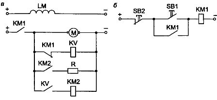
Rice. 8. Node of the circuit for automatic control of dynamic braking in the EMF function: a — power circuit; b — control circuit
Dynamic braking constant motor independent excitation as a function of time is carried out according to the scheme shown in fig. nine.
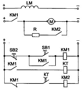
Rice. 9. Node of the DCT dynamic braking circuit of independent excitation as a function of time
When the engine is running, the time relay KT is on, but the circuit of the brake contactor KM2 is open. To stop, you must press the "Stop" button SB2. Contactor KM1 and time relay KT lose power; the contactor KM2 is activated because the contact KM1 in the circuit of the contactor KM2 closes and the contact of the time relay KT opens with a time delay.
For the timing of the time relay, the contactor KM2 receives power, closes its contact and connects the motor armature to the additional resistor R. A dynamic stop of the motor is performed. At its end, the KT relay, after some time, opens its contact and disconnects the KM2 contactor from the network. Further braking to a complete stop is carried out under the influence of the moment of resistance Ms.
In reverse action braking, the motor EMF and the mains voltage act in accordance. To limit the current, a resistor is inserted into the circuit.
Excitation control of DC motors
The field winding of the motor has a significant inductance and if the motor is switched off quickly, a large voltage may appear on it, which will cause the insulation of the winding to break down. To prevent this, you can use the circuit nodes shown in fig.10. The extinguishing resistance is turned on in parallel with the excitation coil through the diode (Fig. 10, b). Therefore, after switching off, the current passes through the resistance for a short time (Fig. 10, a).
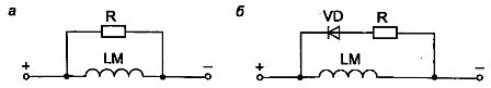
Rice. 10. Nodes of circuits for switching on quenching resistances: a — quenching resistance is connected in parallel; b — the quenching resistance is switched on through the diode.
Protection against interruption of the excitation circuit is carried out using an undercurrent relay according to the scheme shown in fig. eleven.
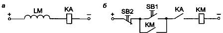
Rice. 11. Protection against interruption of the excitation circuit: a — power excitation circuit; b — control circuit
In the event of a break in the excitation coil, the relay KA de-energizes and disconnects the circuit of the contactor KM.