The most common AC to DC rectification schemes
 A rectifier is an electronic device designed to convert electrical energy from alternating current to direct current. Rectifiers are based on semiconductor devices with single-sided conduction - diodes and thyristors.
At low load power (up to several hundred watts), the conversion of alternating current into direct current is carried out using single-phase rectifiers. Such rectifiers are designed to power various electronic devices with direct current, excitation windings of DC motors of small and medium power, etc.
For an easier understanding of the operation of rectifier circuits, we will proceed from the calculation that the rectifier works on a resistive load.
Single-phase, half-wave (single-cycle) rectification circuit
Figure 1 shows the simplest rectification circuit. The circuit contains a rectifier connected between the secondary winding of the transformer and the load.
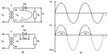
Figure 1 - Single-phase half-wave rectifier: a) circuit - diode open, b) circuit - diode closed, c) timing diagrams of operation
The voltage u2 changes in a sinusoidal manner, i.e.contains positive and negative half waves (half periods). The current in the load circuit passes only in positive half-cycles when a positive potential is applied to the anode of the diode VD (Fig. 1, a). With the reverse polarity of the voltage u2, the diode is closed, the current in the load does not flow, but the reverse voltage Urev is applied to the diode (Fig. 1, b).
Che. only one half-wave of the secondary winding voltage is released across the load. The current in the load flows only in one direction and is direct current, although it has a pulsating character (Fig. 1, c). This form of voltage (current) is called a DC pulse.
Rectified voltages and currents contain a DC (useful) component and an AC component (ripples). The quality side of the rectifier operation is evaluated by the relationship between the useful component and the voltage and current excitation. The ripple factor of this circuit is 1.57. The average value of the corrected voltage for the period Un = 0.45U2. The maximum value of the reverse voltage of the diode Urev.max = 3.14Un.
The advantage of this circuit is its simplicity, the disadvantages: poor use of the transformer, large reverse voltage of the diode, high ripple ratio of the rectified voltage.
Single-phase bridge rectifier circuit
It consists of four diodes connected in a bridge circuit. The secondary winding of the transformer is connected to one diagonal of the bridge, and the load to the other (Fig. 2). The common point of the cathodes of diodes VD2, VD4 is the positive pole of the rectifier, the common point of the anodes of diodes VD1, VD3 is the negative pole.
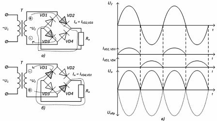
Figure 2-Single-phase bridge rectifier: a) positive half-wave rectification circuit, b) negative half-wave rectification, c) timing diagrams of operation
The polarity of the voltage in the secondary winding changes with the frequency of the supply network. The diodes in this circuit operate in pairs in series. In the positive half-cycle of the voltage u2, the diodes VD2, VD3 conduct current, and the reverse voltage is applied to the diodes VD1, VD4 and they close. During the negative half-cycle of the voltage u2, the current flows through the diodes VD1, VD4, and the diodes VD2, VD3 are closed. The load current flows all the time in one direction.
The circuit is full-wave (push-pull), since both half-periods of the mains voltage Un = 0.9U2, the ripple coefficient — 0.67 are distributed over the load.
The use of a diode switching bridge circuit allows a single-phase transformer to be used to rectify two half-cycles. In addition, the reverse voltage applied to the diode is 2 times less.
Medium and high power consumers are supplied with direct current from three-phase rectifiers, the use of which reduces the current load on the diodes and reduces the ripple factor.
Three-phase bridge rectifier circuit
The circuit consists of six diodes, which are divided into two groups (Fig. 2.61, a): cathode — diodes VD1, VD3, VD5 and anode VD2, VD4, VD6. The load is connected between the connection points of the cathodes and anodes of the diodes, i.e. to the diagonal of the standing bridge. The circuit is connected to a three-phase network.
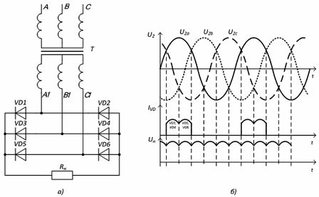
Figure 3 — Three-phase bridge rectifier: a) circuit, b) timing diagrams of operation
At any instant of time, the load current flows through two diodes.In the cathode group, the diode with the highest anode potential operates during every third of the period (Fig. 3, b). In the anode group, in this part of the period, the diode whose cathode has the greatest negative potential works. Each of the diodes operates for one third of the period. The ripple factor of this circuit is only 0.057.
Controlled rectifiers - rectifiers that, along with the correction of alternating voltage (current), provide regulation of the value of the corrected voltage (current).
Controlled rectifiers are used to control the speed of DC motors, the brightness of the glow of incandescent lamps, when charging batteries, etc.
Controlled rectifier circuits are built on thyristors and are based on controlling the opening moment of the thyristors.
Figure 4a shows a diagram of a single-phase controlled rectifier. For the possibility of correcting two half-waves of the mains voltage, a transformer with a two-phase secondary winding is used, in which two voltages with opposite phases are formed. A thyristor is switched on in each phase. The positive half-cycle of the voltage U2 rectifies the thyristor VS1, the negative - VS2.
The CS control circuit generates pulses to open the thyristors. The timing of the opening pulse determines how much of the half-wave is released in the load. The thyristor opens when there is a positive voltage on the anode and an opening pulse on the control electrode.
If the pulse arrives at time t0 (Fig. 4, b), the thyristor is open for the entire half-cycle and the maximum voltage at the load, if at times t1, t2, t3, then only part of the network voltage is released into the load.
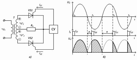
Figure 4 — Single-phase rectifier: a) circuit, b) timing diagrams of operation
The delay angle, measured from the moment of natural ignition of the thyristor, expressed in degrees, is called the control or adjustment angle and is denoted by the letter α. By changing the angle α (phase shift of the control pulses relative to the voltage of the anodes of the thyristors), we change the time of the open state of the thyristors and, accordingly, the corrected voltage in the load.