Electric drive control schemes from multiple locations
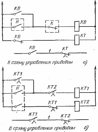
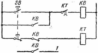
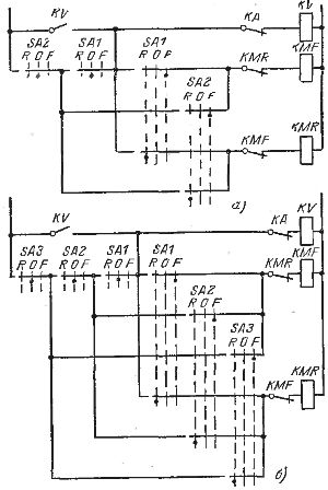
 For continuous process lines, where the drives work mainly in one direction (forward) and reversals are rare, it is recommended to use the circuit (Fig. 1) with the inclusion of a line contactor for "forward" operation through the breaker, and for "reverse" operation — via actuating contacts of the KMR contactor. This arrangement reduces the time to start the drive in the preferred direction.
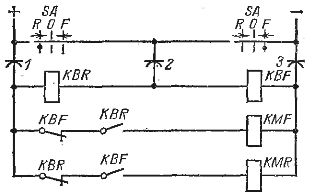
The diagram in fig. 2 allows remote reversible control of the electric motor from a moving object. This circuit is used, for example, to control the motors of the heating well covers from the crane. The signal circuits and reception of various signals are shown in Fig. 3 — 9.
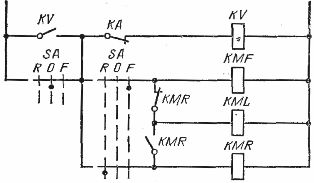
Rice. 1. Rear engine control scheme with rare rear «rear».
Rice. 2. Scheme of reversible control of the motor by means of a control troll.
Rice. 3. Scheme for signaling the status of an irreversible electric drive.
Rice. 4.Circuits for receiving a signal with a time delay after the start of exposure to a long (a) and pulsed (b) signal: K — unlocking contact, 1 — contacts to the control circuit of the drive.
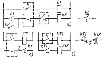
Rice. 5. Schemes for receiving a signal after the end of the beat (from the tail) of the signal H long (a), pulse (b), pulse with a time delay (c). K — unlocking contact, 1, 2, 3 — contacts to the drive control circuit.
Rice. 6. Scheme for receiving a long signal after the beginning of the secondary H.
Rice. 7. Scheme for receiving a pulse signal with a time delay after the secondary action of the signal H (KT1 is 0.2-0.8 s; KT2 0.3 s; KTZ 0.5 s). 1 — contacts to the drive control circuit.
Rice. 8. Scheme for receiving a signal of a certain duration, regardless of the duration of pressing the button: 1 — contact to the drive control circuit.
Counting schemes are used to automatically affect the drive after counting a certain number of operations or cycles. They can count closures and openings (Fig. 10), only closures (Fig. 11), or only openings (Fig. 12).
Counting pulses according to the indicated schemes are supplied from photo relay contacts, motion switches or other devices.
In the counting scheme shown in fig. 10, the REV850 relay is used with a magnetic "sticking" of the armature, and therefore an interruption of the voltage supply to this circuit does not disturb the counting. In other counting circuits, when the voltage supply is interrupted, there is a loss of pulse count.
To check the validity of the account scheme (Fig. 11), control buttons… Each time you press the SB0N button, the circuit performs one count. The SB0F button is used to reset the counter.Such buttons can also be provided in other schemes.
Rice. 9. Circuits for receiving signals in two different circuits by successively pressing one button: a — the duration of the signal is equal to the duration of pressing the button, b — the duration of the signal does not depend on the duration of pressing the button, 1 — contacts to the drive control circuit.
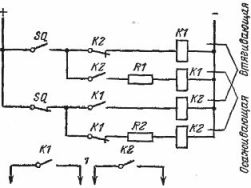
Rice. 10. Scheme of the account up to two.
The pulses for each number are one closing and one opening of the contact of the limit switch SQ; 1 — contacts to the drive control circuit.
Counting pulses in the circuits of fig. 11, 12 are short-term closures (openings) of the SQ contact, and the closed state of this contact should be sufficient to turn on the impulse contactor KNA and one relay KB (KL).
Rice. 11. Scheme for counting to three when contact SQ is closed.
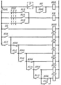
Rice. 12. Scheme for counting to three when opening the SQ contact
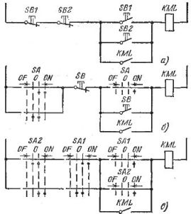
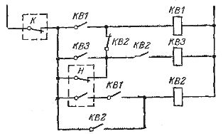
Rice. 13. Schemes of irreversible control of the engine from two places: a — with two buttons, b — with a button and a key, c — with two keys.
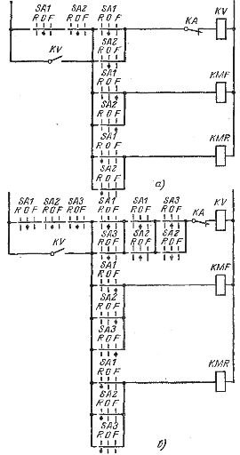
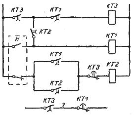
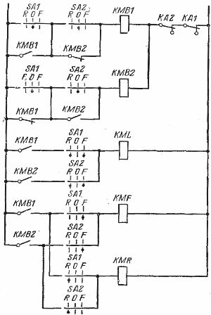
Rice. 14. Scheme of one-sided dependent reversible control of an electric drive from two places.
The count is reset by the KML line contactor; the closed time of the SQ contactor must be less than the on time of the KML contactor.
Counting schemes for a slightly larger number can be drawn up by analogy with the above schemes, but when the count is more than five or eight, or in cases where the loss of counting when the voltage disappears is unacceptable, it is recommended to use numbered relays.
Rice. 15. Schemes of dependent reversible engine control: a — from two places, b — from three places
A type E-526 motor step count relay for up to 30 counts or a type E 531 pulse count relay with up to 75 pulse counts can be used. The relays operate on alternating current and their contacts enable power-off at 220 V respectively AC and DC 50 and 30 watts.
Control circuits of electric motors from several places can be dependent, unidirectionally dependent and independent (Fig. 13). Most often, dependent control schemes are used (Fig. 15) as the simplest. According to these schemes, when operating any control device, moving the handle of another device from zero to the operating position causes the motor to stop.
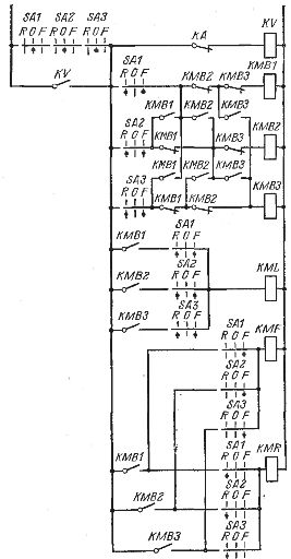
According to the schemes of one-way dependent control from two (Fig. 14) and three (Fig. 16) places, the switch SA1 can be controlled independently of the position of the switch SA2 (SA2 and SA3). Control of the SA2 switch is possible when the SA1 switch is in the zero position and does not depend on the position of the SA3 switch. Control of the SA3 switches is possible when the SA1 and SA2 switches are in the zero position.
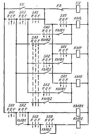
Figure 16. Schematic of the unidirectional dependent control of the three-place reciprocating motor
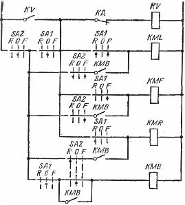
Rice. 17. Scheme of independent reversible control of the engine from two places.
Rice. 18. Scheme of independent reversible control of the engine from three places.
In independent control schemes (Figs. 17 and 18), when the drive is controlled by any first switch (SA1, SA2 or SA3), moving the handle of the other switch does not affect the operation of the drive. After returning to the zero position of the handle of the first key, the actuator will stop regardless of the position of the handle of the second key (or two others). A new start is possible only after returning the second key (or two others) to the zero position.
Very often they use drive control from two and three places according to a simplified scheme (Fig. 19); this means preferential control from only one first place (key SA1). When the drive is controlled by another switch (SA2 or SA3), moving the handle of the first switch from the zero position causes control to be transferred to that switch.
Rice. 19. Simplified schemes for controlling a reversible electric drive: a — from two places, b — from three places.