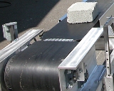
Conveyor drive chains
 The article examines the electrical drive schemes of some conveyors. In fig. 1 shows a schematic diagram of the electric drive of individual conveyor lines, the speeds of which must be strictly the same. Such a need arises in continuous production, when different products, after the necessary technological operations on separate lines, must meet on the assembly site in strict accordance with each other.
The scheme allows you to simultaneously start and stop several conveyor lines and adjust their speed. Coordinated movement is achieved by switching the motors according to the synchronous shaft scheme with a common inverter frequency converter. The speed control of motors D1 and D2 is done by changing the speed of the inverter using a variable ratio gearbox P.
Permission to start conveyors is given by operators who monitor the operation of conveyors in the most critical areas. When the ready buttons G1 and G2 are pressed, the signal lamps LS1 and LS2 light up and the relays RG1 and RG2 are activated. The latter prepare the relay for starting the RP.
When you press the Start button, the RP is triggered, which turns on contactor L1. There is single-phase synchronization of the inverter position, D1 and D2. After time delays, pendulum relays built into contactors L1 and L2 alternately turn L2 on, L1 off, and LZ on. The start of the rheostat of the frequency converter motor is carried out according to the time principle (time relays RU1, RU2, RUZ).
In fig. 2 shows a diagram of the electric drive of the subway escalator, which allows you to work on the rise and fall of passengers. An asynchronous motor with a phase rotor with a power of up to 200 kW is used as a drive motor. At certain times of the day, with an insignificant flow of passengers, the escalator can work almost at idle for a long time.
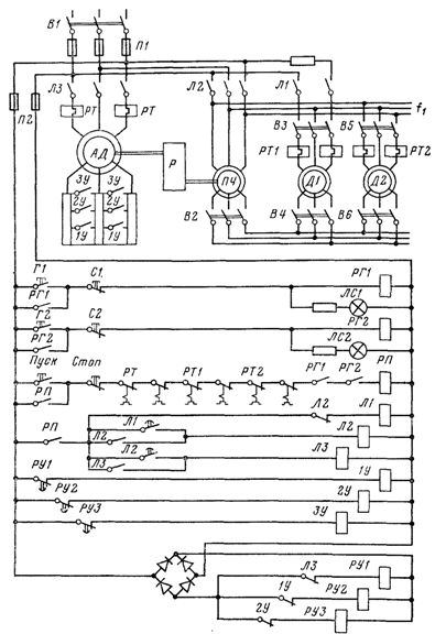
Rice. 1. Scheme of the electrical drive of conveyor lines with coordinated movement.
To increase the power factor and efficiency of the motor, when its shaft load is reduced to about 40% of nominal, the stator winding is switched from delta to star. As the load increases, it turns back into the triangle.
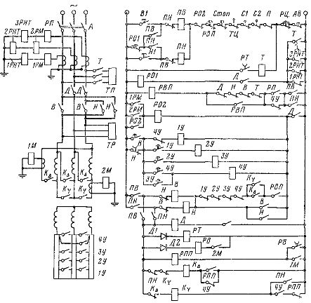
Rice. 2. Scheme of the electric drive of the subway escalator.
Said switching is done automatically by the overcurrent relays 1M and 2M, which control the k∆ and kY contactors through the RPP and РВ relays. The opening delay RV contact ensures the presence of the RPP coil circuit in the period between 2M off and 1M on.
In the generator descent mode with full load, the engine is loaded significantly less (due to mechanical losses of the installation) than with a similar load in the climb mode.Therefore, in droop mode, the stator winding of the motor is always star-connected. The motor is started as a function of time using pendulum relays on accelerator contactors 1U-4U. The stop is mechanical. In this case, the service brake TP is installed on the motor shaft, and the safety TP is installed on the drive gear shaft to ensure that the ladder stops if the mechanical connection between the gear and the motor shafts is broken.
The circuit implements the typical safety interlocks described in the previous section: from a malfunction of the mechanical part of the equipment — removal of chains and handrails (limit switches TC, P), violation of the structure of the steps (limit switches C1 and C2), excessive temperature of the bearings ( thermal relay 7), from overspeed (centrifugal speed relay RC).
In addition, motor protection is provided: maximum (relay 1RM, 2RM), from overload (relay RP), from loss of power from the motor (zero current relay 1RNT, 2RNT, 3RNT), from welding of the closing contacts of power contactors ( opening contacts D, Y, B, T in coil circuit RVP and 1U-4U in coil circuit B).
Protection against power loss, bearing overheating and motor overload operates with a time delay determined by the time relay PO1 and RVP. All protections, except the remote control speed relay, stop the motor by disconnecting it from the mains and applying the TP service brake. Only at the end of the braking process, after the delay of the PT relay has expired, the safety brake TP is additionally actuated.When the RC speed relay is actuated or the emergency stop button is pressed, both brakes are applied simultaneously.