Automatic start, stop and reverse circuits
 Prefab automation schemes are based on the experience of designing, setting up and operating steel plant equipment and can be extended to other industries. The automation of the control processes of electric drives of technological mechanisms is based on the function of position (path), speed, time, pressure, temperature and other quantities characterizing the technological process.
The sensors of these quantities are:
-
travel switches,
-
photo relay,
-
capacitive and induction devices that determine the position of a mechanism or moving body,
-
time devices,
-
contact manometers, etc.
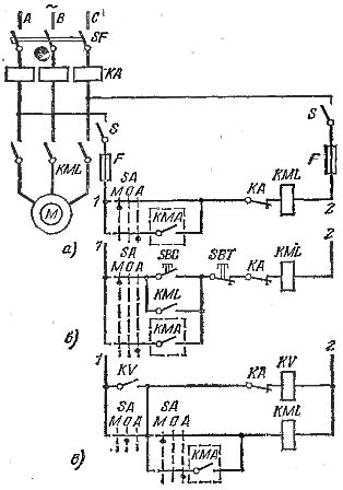
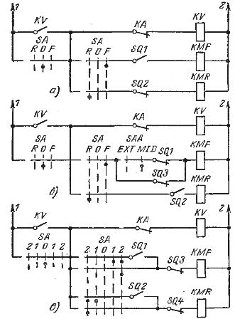
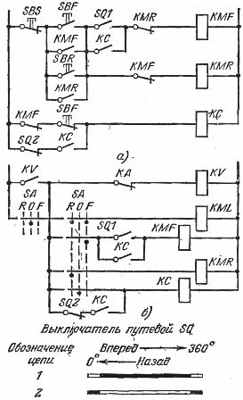
Rice. 1. Schemes of manual and automatic irreversible control of an induction motor with a short circuit. rotor: a — without minimum protection, b — with minimum protection with manual control, c — with minimum protection with manual and automatic control, KMA — automatic signal contact.
The motor control power circuits shown as an example in Fig. 1 and 2 are not shown in the remaining diagrams.
For devices for manual (non-automatic) control, the term «key» is used, made in the form of a command controller, command device, universal switch or other device with a similar action.
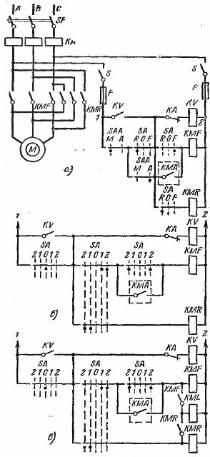
Rice. 2. Schemes of manual and automatic reversible control of an asynchronous motor. Automatic control "forward" only: a — circuit with SAA selector for manual and automatic actuation, manual operation of the SA key turns off the automatic circuit, b and c — circuits with a key without a selector, automatic operation in the first position of the key, KMA — automatic signaling contact.
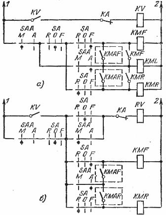
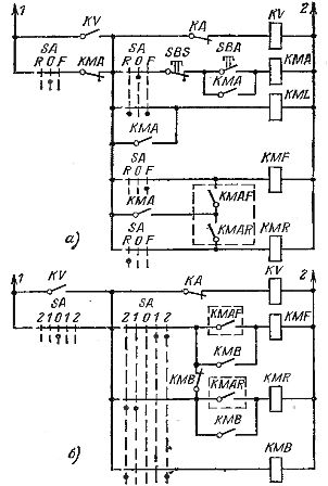
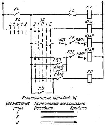
Rice. 3. Schemes of manual and automatic reverse control using a selector: a — during automatic operation, the manual control of the SA key turns off the automatic circuits and the operation of the drive is adjusted by the operator, b — during automatic operation, the transfer on the key SA from the zero position stops the drive, KMAF and KMAR — contactors automatic signals «forward» and «reverse».
Rice. 4. Schemes of manual and automatic reverse control of the drive: a — automatic control is carried out when the KMA contactor is turned on, the circuit allows during automatic operation to switch to manual control with complete shutdown of automation, b — automatic control is carried out externally at key position 1, at key position 2 manual adjustment of the operation of the drive is possible, KMAF and KMAR — contacts of automatic signals «forward» and «reverse».
Rice. 5. Schemes for automatic stop of the drive: a — in the end positions of the working element, b — in the end positions and in the intermediate position "forward" (SAA in the MID position), c — in the end and intermediate positions positions "forward" and " back».
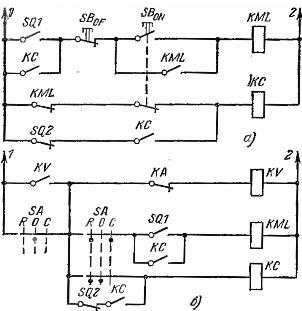
Rice. 6. Schemes of cyclic operation of an irreversible electric drive using two pulleys with a movement switch: a — button control, b — key control.
Rice. 7. Schemes of cyclic operation of an irreversible electric drive using one pulley of a motion switch and a time relay (the minimum time delay is only for closing contact 1 of the motion switch): a — button control, b — key control.
In the diagrams, the designations of the contactors are adopted:
-
KML — linear
-
KMF — forward,
-
KMR — vice versa,
-
KMD — dynamic braking,
-
KMA — automation,
-
KMV — blocking.
Designations of relays:
-
CT — time
-
KA — maximum current,
-
KB, KF, KR — blocking,
-
KS — cyclic,
-
SQ — motion switch.
In electric mechanism drives, automatic control circuit units are widely used: autostart, autostop, cyclic operation, automatic reciprocating-progressive endless motion, or a combination thereof.
Self-starting of the drive can be done by the sensor or devices of other drives in a certain predetermined position of the mechanism.
Automatic stop of the drive can be done in end and intermediate positions or for eccentric mechanisms after turning the eccentric 180 or 360 °. Autoreverse can be used to reverse the mechanism or to continuously operate the mechanism with a reciprocating or rotary motion.
In fig. Figures 8-10 show diagrams with selector for transfer to manual or automatic control and without selector. In selector circuits, during automatic operation, the switch is in the zero position and may prevent automatic operation.
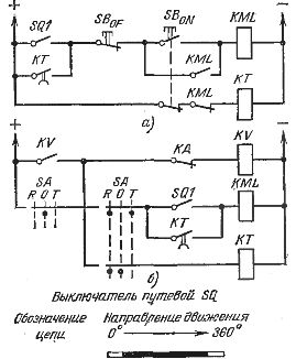
Rice. 8.Schemes of cyclic operation of a reversible electric drive using two pulleys with a switch ("forward" — cyclic operation, "reverse" — continuous operation): a — button control, b — key control.
In circuits without a selector, the first key position is used for manual control and the second for automatic control or vice versa. Although automatic voting circuits have more elements, they are more flexible than those without voters. As a selector, a universal switch or a universal cam switch is usually used, which have a sufficient number of contacts necessary to implement complex circuits.
The selection of manual control devices is based on the frequency of switching on the mechanisms. For frequently operating mechanisms (over 100 starts per hour) command controllers, short-stroke palm buttons and foot buttons are used. Universal switches are used for mechanisms with a number of starts up to 100 per hour. For long-term operating mechanisms, stations with buttons, universal switches and cam switches are used.
Rice. 9. Control circuit with automatic movement to return the working element to its original position.
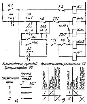
Rice. 10. Scheme of automatic piston endless movement: a — rotary limit switch, b — two limit switches with a lever. The designation SQ1 in the KMR contactor coil circuit is given for the lever limit switches, for a rotary SQ the circuit will be designated as SQ3.