Classification and implementation of substation schemes
 Diagrams of transformer substations and distribution points are divided into primary circuit diagrams, or primary, and secondary circuit diagrams, or secondary circuits.
Secondary circuits include elements of secondary equipment connected to each other in the sequence that ensures the operation of the circuit. Secondary equipment is measuring, protective and automated relay, control and signaling equipment interconnected by wires and control cables. Secondary equipment is used to control the main equipment, its protection, work control.
According to their purpose, schemes are divided into main and assembly schemes.
Schematic diagrams showing the electrical connection between the equipment and the sequence of its operation are drawn up for the installation as a whole or for a separate element of the electrical circuit (for example, a schematic diagram of the power line, a schematic diagram of the line protection).
On the basis of basic primary and secondary circuits, complete circuits are built, including elements of primary and secondary equipment directly connected to the circuit under consideration.
According to the method of presentation, basic and full charts are single- and multi-line, combined (collapsed) and expanded.
On single-line diagrams, all phase wires are conventionally designated as one line, multi-line included — each phase is drawn separately. Only basic primary diagrams are drawn in a single-line image.
On combined diagrams, all equipment and devices in assembled form are represented by symbols and show the electrical connections between them. In extended diagrams, devices and devices are depicted as separate elements connected to each other in a circuit in the direction of current flow from pole to pole.
For clear orientation of devices, devices and their parts are assigned the same letter marking. If the diagram contains several identical devices, they are numbered.
On detailed diagrams, the circuits and their rows are arranged so that the diagram is read from bottom to top and from left to right, or from left to right and from top to bottom.
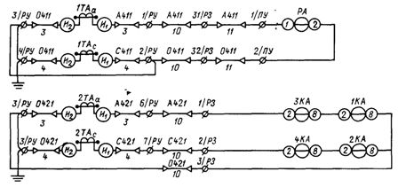
In fig. 1 shows the complete line protection scheme in combined and expanded form. The primary circuit is made in a single line construction. In that part of it, where the current transformers are included in the two-phase wires, the scheme is given in a three-line image. All equipment is marked with letters: Q — switch, Kao — cut-off solenoid, CT — time relay, etc.
Identical devices are additionally marked with numbers. So, in the presence of two current relays, one of them is designated as 1KA, the other as 2KA.If there are two windings in the current transformer, one of them is labeled 1TA and the other 2TA. The extended diagram gives an explanation of the individual circuits. The symbols on the diagrams are applied in accordance with GOST.
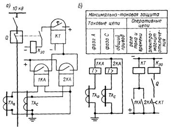
Rice. 1. Complete scheme of the secondary protection circuits: a — combined, b — extended
An electrical diagram is drawn up based on the principle and is a working drawing for installing a secondary switch. Such a purpose requires an image of devices, equipment and terminal clamps on it, arrangement of connecting wires and cables in accordance with their arrangement.
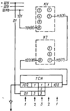
The electrical diagrams are made for individual units of the installation (distribution chamber with a switch, panel of the relay board, etc.), which makes it possible to carry out installation at the same time on all nodes. Diagrams of nodes show the location of devices and devices, as well as the laying of connecting wires to the brackets (Fig. 2).
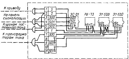
Rice. 2. Wiring diagram of the relay protection panel
The connection of equipment devices located in different places is carried out by connecting wires or control cables from the nodes of the connecting brackets from one block of the installation to another. These external connections are reflected in the cable connection diagram (Fig. 3).
Rice. 3. Wiring diagram
Connection diagrams must clearly mark all devices, devices, clamps, wires and cable cores, as well as control cables (Fig. 4).
Rice. 4. Marking of wires, clamps and core
In the case of complex schemes with many control cables and a long length of connections, a drawing of the distribution of cables is built and a cable log is kept, which shows the marking of the cables according to the connection scheme, their direction, brands, number and cross-section of cores .
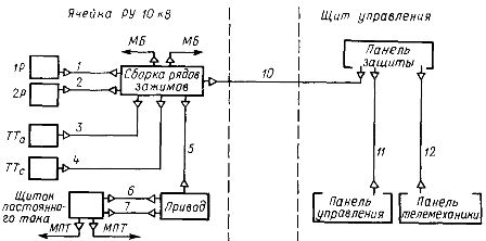
On the basis of the schematic and electrical diagrams, they draw up combined electrical diagrams that reflect the interaction of individual elements of the circuit and make it possible to navigate the installation during commissioning (Fig. 5). The combined schemes, adjusted during installation and commissioning, serve as executive schemes of operation.
Rice. 5. Combined circuit diagram
Primary circuits show the paths of the electrical load at operating voltage from the source to the consumer and combine the equipment elements (transformers, switching equipment) and current-carrying parts (buses, cables).
Primary circuits are subdivided depending on the purpose of the TP or RP, the characteristics of the connected consumers, the power supply scheme, the construction of the TP or RP.
Diagrams with a single busbar system are used to supply several step-down power transformers, as well as to supply electrical receivers connected to the RP.
Schemes run split and non-split. Circuits divided by a switch or disconnector into two or three bus sections are used when supplying consumers of the first or second category of reliability. If automatic redundancy is required, then a sectional switch using the ATS circuit is installed on the busbars.
An example of a split circuit with one busbar system is shown in Fig. 6
Rice. 6.One-line diagram of a transformer substation 6 — 10 / 0.4 kV
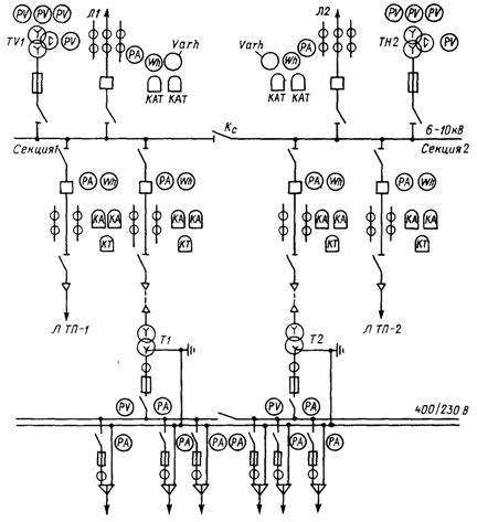
Schemes with two section buses are carried out at large gas transmission stations (Fig. 7), converter substations or when the mode of operation requires a separate supply of consumers.
Rice. 7. Scheme of GPP 110/6 — 10 kV with two transformers with a power of 25 — 63 MVA
Schemes with bypass, bypass bus system they are used when the nature of the user's work requires private operational switching, which is carried out, for example, in furnace substations.
Structure diagrams of substations are performed without buses with higher and sometimes lower voltage. In block diagrams, the TP transformer is connected directly to the line suitable for the substation. The line is connected to the transformer through a switching device or blind connection.
The following block diagrams exist:
-
block line 35-220 kV — GPP transformer,
-
block-line 35-220 kV-transformer GPP-current conductor 6-10 kV,
-
block line 6-10 kV — store transformer transformer,
-
block line 6-10 kV — transformer TP — main conductor 0.38-0.66 kV,
-
block line — transformer — motor.
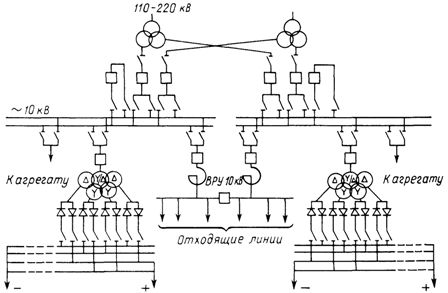
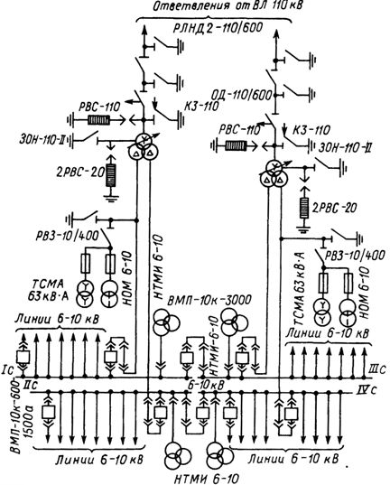
Rice. 8. Scheme of a conversion substation for powering electrolysis plants
Primary substation diagrams show the types of equipment, rated voltages, brands and cross-sections of busbars and cables, etc.