Brake circuits for DC motors
 When braking and reversing DC motors (DPT) applies electrical (dynamic and countershift) and mechanical braking. During dynamic braking, the circuit disconnects the armature winding from the network and closes it to a braking resistor in one or more steps. Dynamic braking is controlled with reference times or with speed control.
To control the torque of the DCT with timing adjustment in the dynamic braking mode, the circuit assembly shown in Fig. 1, a, designed to control DCT braking with independent excitation with a single stage of the braking resistor R2.
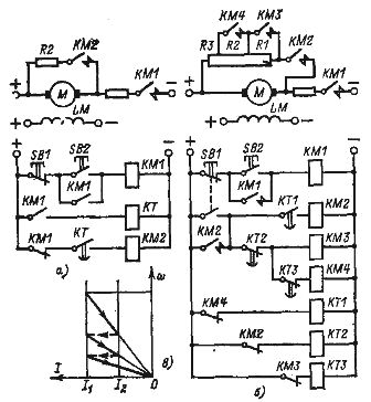
Rice. 1. Schematic that implements single-stage (a) and three-stage (b) dynamic braking of a DC motor with time control and initial diagram of three-stage braking (c).
The command to transfer the DPT to dynamic stop mode in the above diagram is given by the SB1 button. In this case, the line contactor KM1 disconnects the motor armature from the mains voltage, and the braking contactor KM2 connects a braking resistor to it.The command to time the dynamic braking process for the brake relay KT is given to the line contactors KM1, which perform the previous operation in the circuit before the start of dynamic braking. An electromagnetic time relay for DC is used as a brake relay.
The circuit can be used to control independently excited DCTs and series excited DCTs, but in the latter case with current reversal in the series field winding.
DC injection time-controlled braking is most commonly used in multi-stage braking, where multiple timing relays are used to send commands to successive stages of a braking resistor (as in starting). A node of such a circuit constructed for an independently excited DCT with three stages of braking resistor is shown in Fig. 1, b.
The sequential inclusion of the braking stages is carried out by the contactors KM2, KM3, KM4, controlled by the electromagnetic time relays KT1, KT2 and KT3. The control command to start the stop in the circuit is given by the button SB1, which turns off the contactor KM1 and turns on KM2.
The further sequence of turning on contactors KM3, KM4 and turning off KM2 at the end of the braking process is determined by the setting of brake relays KT2, KT3 and KT1, which provide switching at current values I1 and I2, as shown in fig. 1, c. The above control scheme can also be used to control an AC motor in dynamic braking mode.
In single-stage dynamic braking, the most common is torque control with speed control. The node of such a chain is shown in fig. 2.Speed control is provided by the KV voltage relay whose coil is connected to the armature of the DPT.
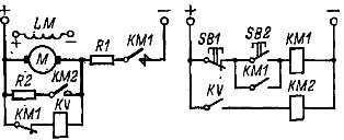
Rice. 2. DC motor dynamic braking control circuit with speed control.
This low speed tripping relay commands the KM2 contactor to turn off and terminate the braking process. The voltage drop of the KV relay corresponds to a rate of about 10-20% of the steady-state initial value:

In practice, the KV relay is set so that the brake contactor is de-energized at near zero speed. As the brake relay must be de-energized at low voltage, then a REV830 type low return voltage relay is selected.
When stopping motors in opposition mode, which is most often used in reversing circuits, the use of speed control is the simplest and most reliable.
The DPT SV control unit in braking mode with a single-stage feedback of the braking resistor is shown in Fig. 3. The braking resistor consists of a conventionally accepted starting stage R2 and an opposing stage R1. The control command for reverse with preopposite braking in the above diagram is given by the SM controller.
The control of the shutdown mode and the issuing of a command to terminate it is carried out by the anti-switching relays KV1 and KV2, which are voltage relays of the REV821 or REV84 type. The relays are adjusted to the pull-up voltage based on its turn-on at engine speed close to zero (15-20% of steady speed):

where Uc is the supply voltage, Rx is the part of the resistance to which the coil of the anti-switching relay (KV1 or KV2) is connected, R is the armature circuit impedance.

Rice. 4.Control circuit assembly of the DC motor control against rotation braking with speed control.
The point of connection of the relay coils to the starting and braking resistors, i.e. the value Rx, is found from the condition that there is no voltage on the relay at the start of the stop when
where ωinit is the angular velocity of the motor at the start of the deceleration.
The broken state of the closing contact of the anti-switching relay during the entire braking period ensures the presence in the DCT armature of the total braking resistance, which determines the permissible braking current. At the end of the stop, relay KV1 or KV2, turning on, gives a command to turn on the opposition contactor KM4 and allows the start of reversal after the end of the stop.
When starting the engine, relay KV1 or KV2 turns on immediately after the control command to start the engine is given. At the same time, the contactor KM4 turns on and off the degree of resistance R1, the winding of the accelerating relay KT is manipulated. After the delay has elapsed, the relay KT closes its contact in the coil circuit of the contactor KM5, which, when actuated, closes its power contact, maneuvering part of the starting resistor R2, the motor goes to its natural characteristic.
When the motor stops, especially in the travel and lifting mechanisms, a mechanical brake is applied, performed by an electromagnetic shoe or other brake. The scheme for turning on the brake is shown in fig. 4. The brake is controlled by a YB solenoid, when it is on, the brake releases the motor, and when it is off, it decelerates.To turn on the electromagnet, its coil, which usually has a large inductance, is connected to the supply voltage through an arcing contactor, for example, KM5.
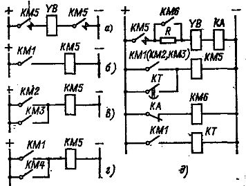
Rice. 4. Nodes of circuits for switching on an electromagnetic DC brake.
This contactor is switched on and off by auxiliary contacts of the linear contactor KM1 (Fig. 4, b) or by the reverse contactor KM2 and KMZ (Fig. 4, c) in reversible circuits. Normally, mechanical braking is performed together with electrical braking, but the brake can be applied, for example, after the end of dynamic braking or with a time delay. In this case, the power supply to the coil of the SW electromagnet during the period of dynamic braking is carried out by the brake contactor KM4 (Fig. 4, d).
Often, the brake electromagnets are turned on by force provided by an additional contactor KM6 (Fig. 4, e). This contactor is de-energized by the current relay KA, which energizes when the brake solenoid YB is energized. The relay KA is configured to operate at a current equal to the rated current of the cold coil of the brake solenoid YB at duty cycle = 25%. The time relay KT is used to ensure that the mechanical brake is applied when the engine stops.
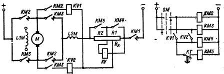
When the DCT is stopped at a speed higher than the basic one, corresponding to weakened magnetic flux, torque control with increasing magnetic flux is performed with current control. Current control is provided by the spacecraft's current relay, which provides relay feedback for the armature current, as was done when the magnetic flux was weakened. In dynamic braking, the circuit shown in fig. 5, a, and when stopped by opposition — the unit shown in fig. 5 B.
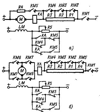
Rice. 5. Nodes of dynamic braking (a) and opposing circuits (b) with increasing magnetic flux of a DC motor with current control control.
The circuits use three stages of the beam resistor (R1 — R3) and three accelerating contactors (KM2 — KM4), one stage of dynamic stop and opposite R4 and one stop contactor (opposite) KM5.
The amplification of the magnetic flux is carried out through the opening contact of the current relay KA, a circuit through which is created when the braking contactor KM5 is turned on, and the circuit of the closing contact KM5, which serves to weaken the magnetic flux when starting, is interrupted by the opening auxiliary contact of contactor KM5.
At the beginning of the deceleration, the KA relay is closed by the pressure of the braking current, and then, when the current drops, it opens and increases the magnetic flux, which causes the current to increase, the KA relay to turn on, and the magnetic flux to weaken. For several switching of the relay, the magnetic flux increases to the nominal value. In addition, dynamic braking and counter-switching will occur in the circuits in accordance with the characteristics determined by resistors R4 and R1-R4.
The KA relay is adjusted in such a way that its switching currents are higher than the minimum value of the braking current, which is important for counter-switching braking.