Connection diagrams of measuring voltage transformers
 The connection diagram of a single-phase voltage transformer is shown in fig. 1, a. Fuses FV1 and FV2 protect the high voltage network from damage to the primary winding of the TV. Circuit breakers FV3 and FV4 (or circuit breakers) protect the TV from damage to the load.
Connection diagram of two single-phase voltage transformers TV1 and TV2 in an open delta (Fig. 2). Transformers are included for two phase phase voltages, for example UAB and UBC. The terminal voltage of the secondary windings of the TV is always proportional to the phase-to-phase voltages supplied from the primary side. A load (relay) is connected between the wires of the secondary circuit.
The circuit allows you to accept all three phase-to-phase voltages UAB, UBC and UCA (it is not recommended to connect the load between points a and c, since additional load current will flow through the transformers, which leads to an increase in error).
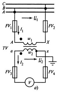
Rice. 1. Connection diagram of a measuring voltage transformer
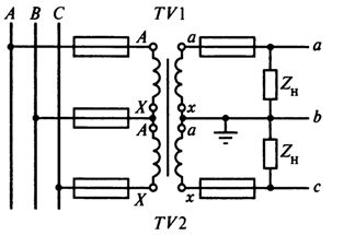
Rice. 2.Connection diagram of two single-phase open-delta voltage transformers
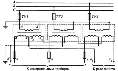
Connection diagram of three single-phase voltage transformers in star shown in fig. 3, is designed to obtain phase-to-ground and phase-to-phase (line-to-line) voltages. The three primary windings of the TV are connected in star. The beginnings of each winding L are connected to the corresponding phases of the line, and the ends of X are united at a common point (neutral N1) and grounded.
With this connection, the phase line voltage (PTL) to ground is applied to each primary winding of the voltage transformer (VT). The ends of the secondary windings of VT (x) are also connected to a star, the neutral of which N2 is connected to the zero point of the load. In the above diagram, the neutral of the primary winding (point N1) is firmly connected to ground and has a potential equal to zero, the same potential will have neutral N2 and the load neutral connected to the neutral.
Rice. 3. Connection diagram of three single-phase star voltage transformers
In this arrangement, the phase voltages on the secondary side correspond to the phase voltages to ground on the primary side. The grounding of the neutral of the primary winding of the voltage transformer and the presence of a neutral conductor in the secondary circuit are prerequisites for obtaining phase voltages with respect to ground.
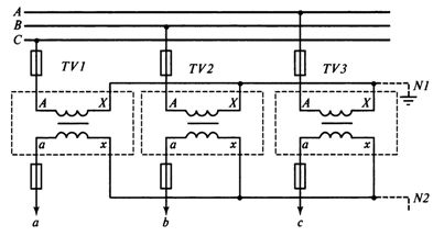
Connection diagram single-phase voltage transformers in the zero-sequence voltage filter (Fig. 4). The primary windings are connected in star with a grounded neutral, and the secondary windings are connected in series, forming an open delta.KV voltage relays are connected to the terminals at the tips of the open delta. The voltage U2 at the terminals of the open delta is equal to the geometric sum of the voltages of the secondary windings:

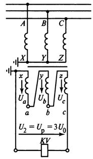
Rice. 4. Connection diagram of three single-phase voltage transformers in a zero-sequence voltage filter
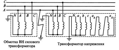
The scheme under consideration is a zero sequence (NP) filter. A necessary condition for the operation of the circuit as an NP filter is the grounding of the neutral of the primary winding of the VT. Using single-phase VTs with two secondary windings, it is possible to connect one of them according to the star circuit, and the second according to the open delta circuit (Fig. 5).
Rice. 5. Connection diagram of three single-phase voltage transformers for insulation monitoring
The nominal secondary voltage of the winding intended for open delta connection is assumed to be equal for networks with earthed neutral 100 V and for networks with isolated neutral 100/3 V.
Connection diagram of three-phase three-way voltage transformer shown in fig. 6. VT neutral is grounded.
Rice. 6. Connection diagram of a three-phase three-pole voltage transformer in a system with a grounded neutral
Connection diagram of the windings of a three-phase voltage transformer in the voltage filter NP shown in fig. 5.
Three-phase three-level VTs cannot be used for this circuit, since there are no paths in their magnetic circuit to close the magnetic fluxes of NP Fo created by current 10 in the primary windings when there is a ground in the network. In this case, the Pho flux closes in air along a path of high magnetic resistance.
This leads to a decrease in the resistance of the NP of the transformer and a sharp increase in АзНАС. Increased current I is caused by unacceptable heating of the transformer, and therefore the use of three-tube voltage transformers is unacceptable.
In five-pole transformers, the fourth and fifth poles of the magnetic circuit are used to close the F0 fluxes (Fig. 7). To obtain 3U0 from a three-phase five-step voltage transformer, an additional (third) winding is made on each of its main legs 7, 2 and 3, connected in an open delta pattern.
The voltage at the terminals of this coil appears only in the event of a short circuit to the ground, when magnetic fluxes occur on the NPs, which are closed along the 4 and 5 rods of the magnetic wire. Five-pole VT circuits allow phase-to-phase and phase-to-phase voltages to be obtained simultaneously with the NP voltage. They are used for voltage measurement and insulation monitoring in networks with isolated neutral. For the same purposes, you can use the diagram in fig. 5 with three single-phase VTs.
When measuring the power or energy of a three-phase system, the voltage transformer connection circuit shown in Fig. 8.
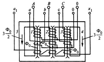
Rice. 7. Ways to close zero-sequence magnetic fluxes in a three-phase five-pole voltage transformer
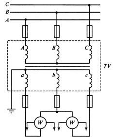
Rice. 8. Connection diagram of a three-phase three-pole voltage transformer for measuring power by the method of two wattmeters