Connection diagrams of circuit elements
 Schemes of switching on the elements of an electric circuit allow you to visually trace what is the sequence of switching on electrical devices in the circuit and what changes occur in the circuit during its operation after switching on, i.e. circuit diagrams help analyze the performance of a circuit over time. In the process of analysis, according to the switching scheme, it is seen whether this scheme ensures the normal operation of the machine, mechanism or installation in operating modes and how it will act in emergency modes.
To build a diagram for the inclusion of circuit elements, horizontal parallel lines are drawn, the number of which must match the number of electrical devices in the circuit. Each row is marked with the name of its electrical apparatus. Time is measured along these lines and the time scale for all devices is assumed to be the same.
Management of controls (buttons, switches, switches, etc.), i.e. Single-position elements are represented by rectangles. The rectangle shows the moment of closing and opening of the device in the circuit.The operation of electrical devices with coils (electromagnetic starters, intermediate relays, time relays, etc.) is shown with trapezoids. The height of all trapezoids is the same, and the length is determined by the delays during operation. If any apparatus acts on another, then this process is indicated by an arrow.
Let's look at the operation of the control circuit of the drain pump using the circuit diagram of the circuit of elements.
Drainage pumps are designed for pumping underground and rainwater from underground transport galleries. To collect water, the galleries are arranged with a slight slope, at the end of which there are drainage pits. Given that groundwater in rainwater can disable the production mechanisms, two pumps are used for them: a working one and a backup one. The control scheme of irreversible electric drives of drain pumps with an automatic switch is shown below.
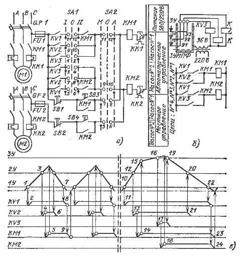
Rice. 1. Schematic control diagram of irreversible electric drives of drainage pumps with automatic reserve input (a), auxiliary circuit (b) and diagram of the operation of its elements (c).
As a result of a preliminary study of the automation scheme, the following was found:
1) The pump control structure provides local and automatic control,
2) automatic control is performed by: KV1 — lower level relay, KV2 — upper level relay, KV3 — upper level alarm level relay. When the level in the sump rises to the point where the KV2 relay is actuated, the pump turns on. When the level drops to normal, the KV1 relay is released, the pump stops.If one pump cannot cope with the pumping and the level continues to rise, the alarm relay KV3 is activated and the second pump is switched on. When the level drops to normal, both pumps are turned off,
3) for uniform operation of the pumps, it is possible to change the sequence of turning on the pumps during automatic control.
To understand more clearly the operation of the circuit under automatic control, we will use a general technique which is as follows.
We create an auxiliary circuit (Fig. 1, b) and depict on it a crankcase with markings: 1U — lower level, 2U — upper level, 3U — upper emergency level. We release the electrodes E1 — E3 to these marks and connect them to the relay KV1 — KV3, respectively.
We make a copy of the diagram (fig. 1, a), showing on it only the connections of the contacts of the relays KV1 and KV2 with the magnetic starter KM1 of the first pump and the contact of the relay KV3 with the magnetic starter KM2 of the second pump.
Next, we build a diagram for the inclusion of the elements of the circuit (Fig. 1, c) and reflect on it the processes of filling and pumping the shaft and the dependence on the position of the relay.
In the diagram, the lines 1U — 3U correspond to three levels, and the dashed line corresponds to the drained sump.
The cap begins to fill, the water in it reaches the 1U level (point 1 in the diagram). In this case, the relay circuit KV1 closes, the relay is activated (point 2) and closes the contact in circuit No. 1 (see Fig. 1.6), but the magnetic starter KM1 does not turn on, since the closing contact KM1 is connected in series with the relay contact KV1 .
When the level 2U (point 3) is reached, the relay KV3 (point 4) turns on and on circuit No. 2 turns on the magnetic starter KM1 (point 5) and pumping begins.Soon the KV2 relay is released (point 6), but the pump does not turn off, since the KV1 coil continues to receive power through circuit #1 through contacts KV1 and KM1. Finally, the level drops to normal (point 7), the KV1 relay releases (point 8) and turns off the magnetic starter (point 9). After some time, when the water accumulates in the shaft, everything is repeated in the same sequence.
If rainwater is added to the groundwater, then the filling of the shaft proceeds more intensively (line 10 — 12 is steeper than line 1 — 3). At point 10, relay KV1 (point 11) turns on and prepares circuits #1 and 3. When level 2U (point 12) is reached, relay KV2 (point 13) is activated and turns on KM1 through circuit no. 2 (point 14). From this moment (from point 15) the level increases less intensively (line 15 — 16 is positioned under line 10 — 12), since one pump is already working.
At level 3U (point 16), relay KV3 (point 17) activates and turns on KM2 (point 18), the second pump starts working. The level drops, at point 19 it releases KV3, but the second pump continues to work, since KM2 receives power from circuit No. 3. At point 20, the KV2 relay turns off (point 21), but the first pump does not turn off, since KM1 receives power through circuit No. 1. Finally, at point 22 it releases KV1 and turns off the two magnetic starters (points 23 and 24), the pumps stop ...