Diagrams of electric actuators with an electric motor
 Electric actuators with an electric motor are designed to move various bodies of shut-off and control pipeline valves with a rotary principle of action (ball and plug valves, throttle valves, dampers).
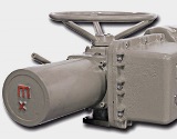
The main units of the drive are: electric motor, reducer, manual drive, position signaling unit. Mechanisms use synchronous and asynchronous AC motors. Speed reduction and torque increase are accomplished using combined worm and gear gears. Manual control is done using a hand drive. Hitting the handwheel by pushing on the shaft axis with the engine stopped causes the handwheel to engage with the motor shaft and transmit torque to the output shaft.
Electric motor drives are single-turn and multi-turn, positional and proportional. A diagram of a two-position actuator with a two-phase capacitor motor is shown in Fig. 1 (a).
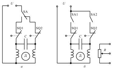
Rice. 1.Schemes of actuators with two-phase electric motors: a-diagram of two-position actuator; b — diagram of a proportional actuator
The switch SA sets the direction of rotation of the rotor of the electric motor, connecting the capacitor C to either one or the other winding of the electric motor. If switch SA closes the circuit containing SQ1, then the electric motor turns on and moves the actuator output element until it reaches the end position and switches limit switch SQ1. In this case, contact SQ1 will open, the motor will turn off. To move the output organ to the other end position, it is necessary to switch the SA. The motor is reversed and will run until the SQ2 limit switch contact opens.
A diagram of a proportional actuator is shown in Fig. 1 (b). Closing the SA1 contact causes the drive output element to move in the forward direction, and closing SA2 in the reverse direction. By opening the contact, you can stop the mechanism in any intermediate position of the output element. Potentiometer R is used as a position transmitter. Limit switches SQ1 and SQ2 turn off the electric motor in the end positions, protecting the mechanism from damage.
A diagram of a drive mechanism with a three-phase electric motor is shown in Fig. 3.
Such an actuator can be used, for example, to control a valve. The circuit contains the contactor KM1, which includes a mechanism for opening the actuator valve, with the opening button SB1 and the contactor KM2 with the closing button SB2. The limit switch SQ1 is actuated in the closed end position.In the diagram, the limit switches are shown in the middle position of the valve, none of them work.
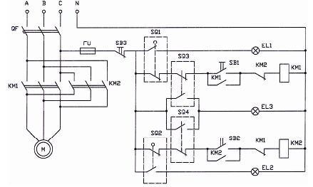
Rice. 2. Scheme of the drive with a three-phase electric motor
When you press the SB1 button, KM1 will work and turn on the electric motor to open the shutter. In the fully open position, SQ1 will work and with its opening contact it will turn off KM1 and, accordingly, the electric motor, and with its closing contact it will turn on the signal lamp EL1 «open».
If you then press the SB2 button, then KM2 will operate and turn on the electric motor to close the valve. When the valve is closed, SQ2 will operate, turn off KM2 and activate the closed alarm (EL2).
The drive mechanism is equipped with a torque limiting clutch. If the shaft torque is exceeded, for example, when the valve is stuck during the opening process, the switch SQ3 will turn off and turn off the electric motor by turning off the contactor KM1. If the mechanism is stuck during the closing process, SQ4 will operate and shut down KM2 and the electric motor. Both switches, when actuated, illuminate the "trouble" indicator light on EL3. The SB3 button can be used to stop the engine in the intermediate valve position.