Conventional graphic symbols of electrical circuits
An electrical diagram is a text that describes the content and operation of an electrical device or set of devices with certain symbols, which allows this text to be expressed in a concise form.
To read any text, you need to know the alphabet and reading rules. So, to read the schemes, you need to know the symbols — the symbols and the rules for decoding their combinations.
The basis of any electrical circuit is represented by conventional graphic symbols various elements and devices, as well as connections between them. The language of modern diagrams emphasizes in symbols the main functions performed by the element depicted in the diagram. All the correct conventional graphic designations of elements of electrical circuits and their individual parts are given in the form of tables in the standards.
Graphic symbols are formed from simple geometric figures: squares, rectangles, circles, as well as from solid and dotted lines and dots.Their combination according to a special system provided by the standard makes it possible to easily depict everything necessary: various electrical devices, devices, electrical machines, lines of mechanical and electrical connections, types of winding connections, type of actuality, nature and methods of regulation, etc.
In addition, special symbols are additionally used in the conventional graphic symbols of electrical schematic diagrams to explain the characteristics of the operation of one or another element of the circuit.
For example, there are three types of contacts—make, break, and switch. The legend reflects only the main function of a contact — closing and opening a circuit.
To indicate additional functionality of a particular contact, the standard provides for the use of special characters applied to the image of the moving part of the contact. Additional characters allow you to find contacts on the diagram control buttons, time relays, limit switches, etc.
Individual elements of electrical circuits have not one, but several designations on the diagrams. For example, there are several equivalent designation options for switching contacts, as well as several standard designations for transformer windings. Each of the designations can be used in certain cases.
If the standard does not contain the required designation, it is compiled based on the principle of operation of the element, the designations adopted for similar types of devices, devices, machines in accordance with the design principles provided for in the standard.
Electrical devices and their parts in the diagrams are depicted in the normal position, that is, when there is no voltage and no mechanical stress is applied to the devices. In other words, the armatures of all relays, contactors, etc. are released, switches, disconnectors, switches, etc. are prohibited.
If the devices can have only two positions (on — off, armature pulled — released, button pressed — released, etc.), then their contacts are divided into normally closed (NC) and normally open (NO).
In the normal position of the apparatus, normally closed contacts are closed (closed) and normally open contacts are open (open). Normally open auxiliary contacts are open and normally closed contacts are closed when the circuit breaker to which they are connected is tripped.
Diagrams, as a rule, give diagrams of the operation of keys or kinematic drawings (tables) explaining the operation of complex devices. In simple cases, GOST does not allow giving tables.
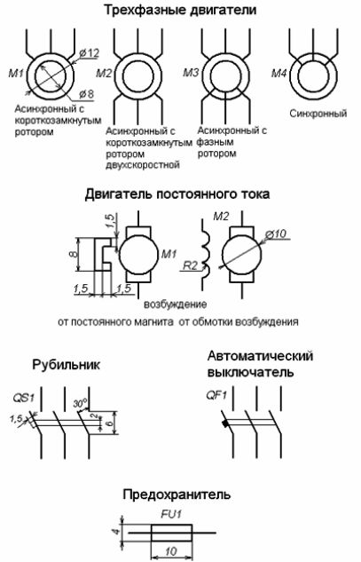
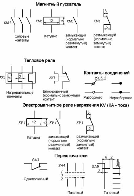
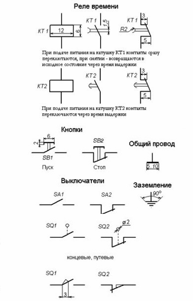
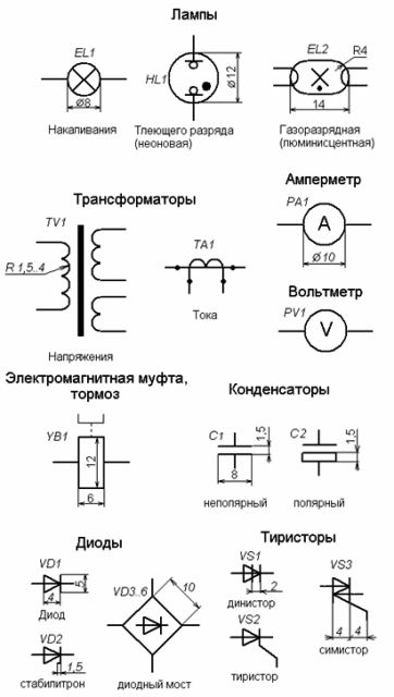
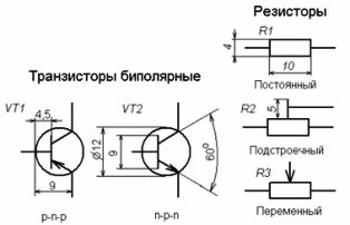
Symbols and dimensions of some elements of schematic diagrams:
Standards. Conventional graphic symbols of electrical circuits and automation circuits:
GOST 2.710-81 Alphanumeric designations in electrical circuits: download GOST 2.710-81
GOST 2.747-68 Dimensions of conventional graphic symbols: download GOST 2.747-68
GOST 21.614-88 Conditional graphic images: download GOST 21.614-88
GOST 2.755-87 Switching devices and contact connections: download GOST 2.755-87
GOST 2.756-76 Sensitive part of electromechanical devices: download GOST 2.756-76
GOST 2.709-89 Designation of conventional wires and contact connections: download GOST 2.709-89
GOST 21.404-85 Designations of automation devices and equipment: download GOST 21.404-85