Electrical Equipment and Electrical Schematic Diagram of the Model 2A55 Radial Drilling Machine
Drilling machines are used to obtain through and blind holes in parts by means of drills, to ream and finish holes previously obtained by casting or stamping, and to perform other operations. In boring machines, the main motion and the feed motion are transmitted to the tool. General purpose machines include vertical drilling and radial drilling machines.

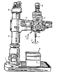
In fig. 1 shows a general view of a radial drilling machine. The machine consists of a base plate 1 with a fixed column mounted on it, on which a hollow sleeve 2 is placed. The sleeve can be rotated around the column 360 °. A horizontal sleeve (stroke) 4 is placed on the sleeve, which can be raised and lowered along the column using the vertical screw of the movement mechanism 3.
The bushing is attached to the column (column clamping) with a split ring that is pulled together using a differential screw turned by hand or with a separate electric motor.The chuck (drilling head) 5 can move along the horizontal guides of the sleeve 5. The workpiece is mounted on a table 8. From the main electric motor 6, the rotation is communicated to the spindle 7 and the tool (drill) is fed.
In electrical engineering, drilling machines are used to drill holes in the ends of beds of electrical machines, in bearing shields, pawls, etc.
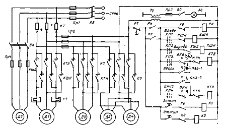
Consider an electric drive and control circuit (Fig. 2) radial drilling machine model 2A55 intended for processing holes with a diameter of up to 50 mm with HSS drills. The machine has five squirrel-cage asynchronous motors: spindle rotation D1 (4.5 kW), traverse displacement D2 (1.7 kW), hydraulic column clamping DZ and spindle head D4 (0.5 kW each) and electric pump D5 (0.125 kW).

The spindle speed of the radial-drilling machine 2A55 is adjustable mechanically using a gearbox in the range from 30 to 1500 rpm (12 speeds). The feed drive of the radial-drilling machine is made by the main motor D1 through the feed box. The feed rate is adjustable from 0.05 to 2.2 mm/rev., the largest feed force Fn = 20,000 N.
The traverse of the radial drilling machine can rotate around the axis of the column 360 ° and vertically move along the column by 680 mm at a speed of 1.4 m / min. The clamping of the traverse on the column is done automatically. All machine controls are centered on the drill, resulting in a significant reduction in machine shutdown time.
All electrical equipment of a radial drilling machine, except for the electric pump, is mounted on the rotating part of the machine, therefore the mains voltage 380 V is supplied through the input switch BB to the ring pantograph KT, and then through the brush contact to the cabinet to switch the traverse.
Before starting the machine, it is necessary to clamp the column and the spindle head, which is done by pressing the button Clamp… Gets power contactor The short circuit and main contacts include DZ and D4 motors that drive hydraulic clamping devices. Simultaneously through an auxiliary contact contactor The short circuit includes the PH relay, which prepares power to the control circuits through its contact after the action on the short circuit contactor's clamp button stops and closes.
To squeeze the column and spindle head, if you need to move them, press the Spin button, at the same time it loses power from the PH relay, making it impossible to operate the machine with the column and spindle head pushed out.
Motor control of the spindle D1 and the movement of the traverse D2 is carried out with the help cross switch KP, the handle of which can be moved to four positions: Left, Right, Up and Down Down, closing contacts KP1 — KP4 respectively. So, in the Left position of the handle, the KShV contactor turns on and the spindle rotates counterclockwise. If the handle is moved to the Right position, then the KSHV contactor turns off, the KSHN contactor turns on, and the machine spindle will rotate clockwise.
When the gear selector lever is placed, for example, in the Up position, contactor KTV engine D2. In this case, the lead screw of the movement mechanism rotates at first idle, moving the nut that sits on it, which causes the traverse to be squeezed (in this case, the PAZ-2 contact of the automatic clamping switch is closed), after which the traverse raises
When the traverse reaches the required level, the gearbox handle is moved to the middle position, due to which the KTV contactor turns off, the K.TN contactor turns on, and the D2 motor turns. Its reverse stroke is necessary for automatic tightening of the traverse due to the rotation of the lead screw in the opposite direction and the movement of the nut to the tightening position, after which the motor is turned off by the open contact PAZ-2. If you now put the gear selector handle in the Down position, then first the traverse will be drained, then it will be lowered, and so on.
The movement of the traverse in end positions is limited by the limit switches VKV and VKN, which interrupt the supply circuits of the contactors KTV or KTN.
Short-circuit protection in power circuits, control and lighting circuits is provided by fuses Pr1 — Pr4. The spindle motor is protected from overload by a thermal relay PT. The PH relay provides zero protection, preventing self-starting of motors D1 and D2 engaged by the gearbox switch when the supply voltage is removed and then restored. Restoring the control circuit is only possible by pressing the Bracket button again.
