Conventional graphic symbols of electrical machines on the diagrams
 Conventional graphic symbols of electrical machines (GOST 2.722-68). There are three ways to display electrical machine designations: simplified single-line, simplified multi-line, and extended. In fig. 1 a, b show simplified one-line designations of a three-phase generator and AC motor, and in fig. 1c is a simplified multi-line representation of a three-phase asynchronous motor with a phase rotor whose winding is star-connected.
Extended designations of electrical machines can be depicted in the form of chains of circles located taking into account the phase shift (Fig. 1d) and without it (Fig. 1e). The rotor winding is indicated as a circle.
The designations of DC machines with series, parallel and mixed excitation are shown in Fig. respectively. 1 f, g, h. The armature of these machines is shown as a circle with rectangles in contact with it — collectors and brushes.
In fig.1i … l show simplified diagrams, respectively: a three-phase synchronous machine with an excitation winding on a salient-pole rotor and a star-connected stator winding, an induction motor in which the stator winding is delta-connected, a synchronous machine with a permanent magnet excitation and a winding of star connected stator...
In fig. 1m shows the simplified, and fig. 1 and a detailed designation of a rotating three-phase autotransformer (potential regulator) and in fig. 1, o, n-three-phase rotary transformer-phase regulator.
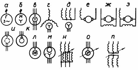
Rice. 1. Symbols of electrical machines on the diagrams
Conventional graphic designations of transformers and autotransformers according to GOST 2.723-68 are shown in fig. 2. Thus in fig. 2 a, b shows simplified one-line designations of three-phase two-winding transformers and autotransformers.
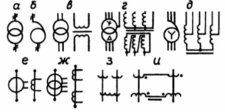
Rice. 2. Symbols of transformers, autotransformers and magnetic amplifiers on diagrams
A simplified multi-line and expanded designation of a single-phase two-winding transformer is shown in Fig. 2 c, in fig. 2 f and g — three-phase two-winding transformers and autotransformers, and in fig. 2 f and g — measuring transformers with one and two windings.
In fig. 2h and 2i show the diagram designations of magnetic amplifiers with two operating and common control coils, respectively, as well as with two operating coils connected in series and a control coil consisting of two oppositely connected coils.
GOST 2.722-68 ESKD. Conventional graphic notations in diagrams. Electric machines: download GOST 2.722-68