Conventional graphic symbols of switching devices on the diagrams
 Conventional graphic designations of switching devices and contact connections (GOST 2.755-87). Switching devices have movable and fixed contact parts. Conditional graphic designation of the contacts of switching devices can be done in a mirror image.
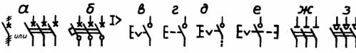
Figures 1a — 1d show the general designation of the make, break, change-over and neutral center position contacts. In figure 1e, f the contacts break without self-recovery, and in figures 1g, l - with self-recovery. In fig. 1 and. The contacts of the contactor are shown in figures 1k, l, respectively, which make and break without arcing.
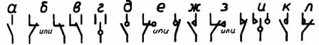
Rice. 1. Symbols of switching devices
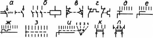
In fig. 2a — c show graphical representations of the contacts, respectively: closing and opening of the arc and closing with automatic operation (fig. 2a, b, c), switch, disconnector and switch disconnector (fig. 2d, e, f), closing and opening limit switch contacts (Fig. 2g, h), temperature sensitive (Fig.2i, j) closing and opening, closing contacts with delay acting on actuation, on return, on actuation and return (Fig. 2l, m, n ), opening contacts with delay acting on actuation, on return, on actuation and return (fig. 2p, p). The delay occurs when moving in the direction from the arc to the center. In fig. 2c shows the closing contact of a single-pole switch.
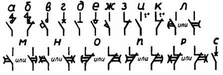
Rice. 2. Symbols of switching devices
Figures 3a, b show the closing contacts of a three-pole switch, without automatic tripping and with automatic maximum current reset, respectively. The closing contacts of a push-button switch without self-recovery with opening and return from the control element are shown in fig. 3c, d, e, f respectively: automatically by pressing the button a second time, by pulling it, by means of a separate device, for example, pressing the reset button.
A three-pole disconnector and a switch-disconnector are shown in fig. 3g, h.
Rice. 3. Symbols of switching devices
In fig. 4, a — d show respectively: manual switch, electromagnetic switch (relay), limit switch with two separate circuits and thermal self-regulating switch.
Rice. 4. Symbols of switching devices
Single-pole switches are shown in Figure 4g-h, respectively: six-position continuous switching with a movable contact that closes three circuit connections in each position, multi-position with a movable contact that closes three circuits, except for one intermediate, multi-position independent circuits , an example of six schemes. The position diagram is connected to the movable contact of the switch by a mechanical link (Fig. 4i).
GOST 2.755-87 Switching devices and contact connections: download GOST 2.755-87