Old designations of elements on machine diagrams
 When creating modern electrical circuits, conventional designations of elements (conventional graphic images) are used in accordance with the current GOST.
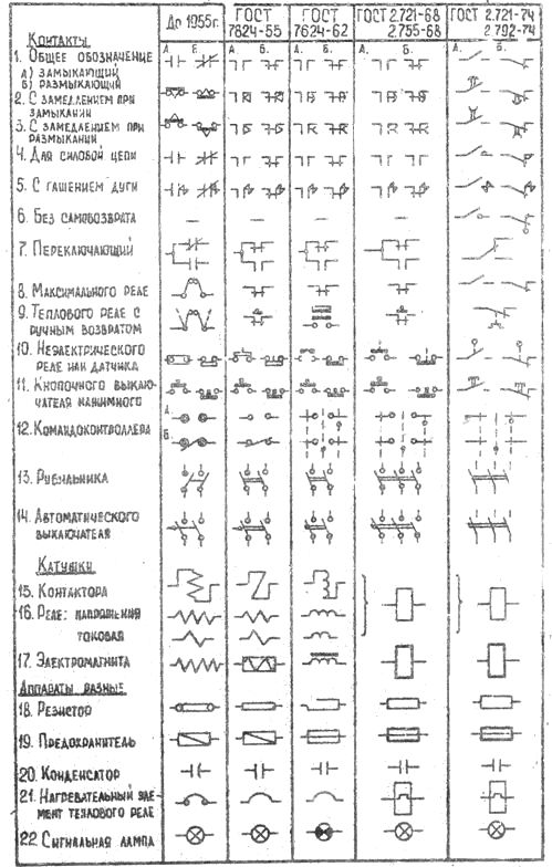
Very often, in the practice of servicing electrical equipment in enterprises, one has to deal with electrical circuits made according to the old GOSTs of 1955, 1962 and 1968. The old designations of diagram elements are used in all schemes of machines, machines and mechanisms, as well as those issued before 1981, as well as in old books. This article contains a table that shows all the main old designations and their analogues in accordance with GOST 1981.
For a long time, there was no single standard for conventional graphic designations of electrical circuit elements. Designations adopted by a number of leading design organizations were used in electric drive control schemes. In 1955, GOST 7624-55 was issued, which legalized the most successful of these designations.In the future, due to the desire to create universal designations that meet the requirements not only of electrical engineering, but also of other industries, the standards changed several times, sometimes, unfortunately, not for the better.
The table clearly shows the process of changing the conventional graphic designations of the elements of the relay-contactor control circuits of electric drives.
It should be noted that in a number of industries departmental standards and technical guidelines have been in force that clarify or slightly modify some of the conventions. The construction of metal-cutting machines also belongs to such industries, and therefore in the electrical equipment of metal-cutting machines there may be some designations that differ from those given in the table.
A few examples of old machine tool schematics
Vertical drilling machine model 2A125: 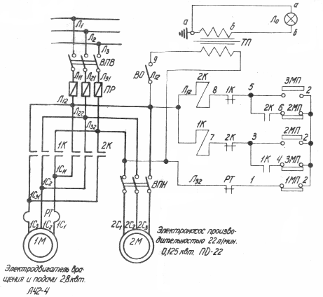
On the diagram: VPV - package switch, PR - fuses, 1K and 2K - magnetic starters, RT - thermal relay, 1MP - "general stop" button, 2MP and 3MP - control buttons with paired contacts "start" and "stop", TP — step-down transformer, Lo — local lighting lamp.
Slotting machine model 7M430:
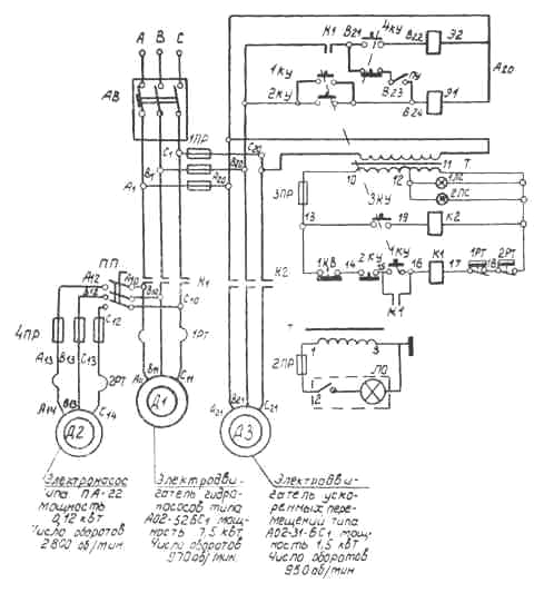
On the diagram: AB — circuit breaker, PR — fuses, K1, K2 — magnetic starters, PP — package switch, 1RT, 2RT — thermal relays, KU — control buttons, E1 and E2 — electromagnets.
New chart designations: Conventional graphic symbols of electrical circuits