Electrical schematics included in the design of the production line
Arrangement of a production line for the processing of root and tuber crops
The stock of root crops is stored in the loading hopper 1. When processing fodder in the lower part of the hopper, open the valve and the roots are fed by gravity onto the inclined conveyor 2, which feeds them into the separator stone 3, from which they go to the cutter for washing roots 4. The crushed roots are then fed into the steam baths 5 of the feed plant or into the cart 6 of the air path for transport to another room.
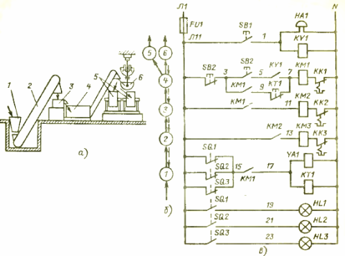
Rice. 1. Production line for processing root and tuber crops
This line is a typical conveyor system. In such a system, to ensure proper operation, blocking of mechanisms is provided, i.e. setting a certain sequence of their start and stop and, as a rule, blocking is done in the direction opposite to the direction of the process flow.
To control such a line, an electrical control circuit (electrical circuit) is used (Fig. 1, c).It shows the launchers of the respective mechanisms. To establish the correspondence of the diagram with the technological process, a technology diagram and blocks are shown to the left of the diagram (Fig. 1, b).
The principle of operation of the electrical circuit
The hopper has a damper closing solenoid YA1. To control mechanisms 2-4, respectively, starters KMZ-KM1 are provided for control-button SB2. The SB1 button is designed to give a start signal, the warning lamps HL1 -HL3 — to signal the working states of mechanisms 5 and 6.
To start the line into operation, press the button SB1 to give a pre-start signal, the bell of HA1 rings, the relay KY1 is activated, closing its contact in the circuit of the first starter KM1 for starting. Then, without releasing the SB1 button, press the SB2 button, turning on the starter KM1, then the starters KM2 and KMZ are started through the contacts of each other, the solenoid YA1 is activated, opening the damper. All machines are included in the work, root and tuber crops are processed.
The operation of the line continues until the steam baths 5 or the trolley body 6 are filled. This will be signaled by their limit switches SQ1 — SQ3, respectively. Their signal opens the supply circuit of the electromagnet YA1 and the time relay KT1. The electromagnet releases the hopper valve 1 and it, under the action of the return spring, blocks the flow of root crops to the conveyor 2 and beyond.
The time relay KT1 installed in the circuit is designed to modify the line, i.e.after switching off the hopper 1, the machines continue to work for some time, necessary for the complete cleaning of the machines from the residues of root crops. After this time, the relay turns off all mechanisms with its contact. For manual braking, the circuit has a contact to open the SB2 button.
One-line power supply diagram of a production line
It is most convenient to concentrate all control equipment in the control panel. In this case, the power supply scheme of the machines is shown in fig. 2.
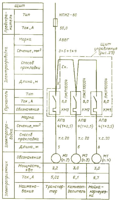
Rice. 2. One-line power supply diagram of the production line
The fuse is installed in the feed store power panel. Starters without protective covers of the PML series are installed in the panel and are equipped with electric protection thermal relay RTL -1012 for a current of 8 A, with an adjustment range of 5.5 — 8 A. The specific protection current is adjusted according to the motor current.
The KM1 starter is supplied with contact attachment PKL-2204 because the circuit requires three auxiliary contacts to operate and it has only one closing auxiliary contact.
The power supply scheme of electric drives, as a rule, is given in a single-line image. It shows power switching devices, electrical wiring and ways to lay them.
Schematics of the control board and circuit diagram of the electrical equipment in the board
Next, a drawing is made of the control panel on which the control equipment is located (Fig. 3). The following equipment is accepted for installation: signal lamps HL1-HL3 (AC-220), buttons SB1 (PKE122-1UZ), SB2 (PKE622-2UZ), relay KY1 (RPU-2M, 2z), KT1 (VL-18- 1 ), fuse FU1 (PRS-6-P), current insertion 6 A, terminal block XT (BZ-10).
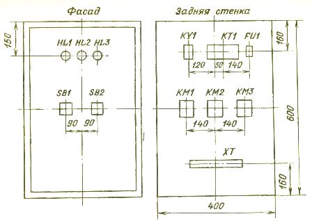
Rice. 3. General view of the control panel with the layout of the electrical equipment
Next, a drawing of the connections of the printed circuit board (electrical diagram - Fig. 4) is shown, on which the electrical diagrams of the installed electrical equipment are drawn without observing the scale, serial numbers (in the numerator) and positional designations according to the diagram principle (in denominator) are placed above each image.
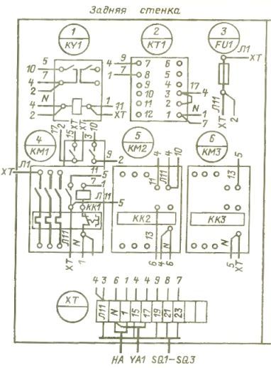
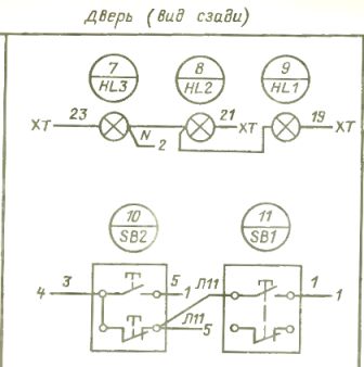
Rice. 4. Wiring diagram of electrical equipment in the control panel
Installation is carried out in one of the ways, for example, by the method of opposite addresses, in which segments of wires are depicted on the corresponding terminals of the equipment, on which the brand of the wire is written according to the schematic diagram, and when the device number is indicated at the end, to which this wire is directed. On the opposite device, the same wire is marked with the number of the previous device.
Switchboard and electrical equipment connection diagram
Next, a diagram of the connection board and electrical equipment is drawn up (Fig. 5). 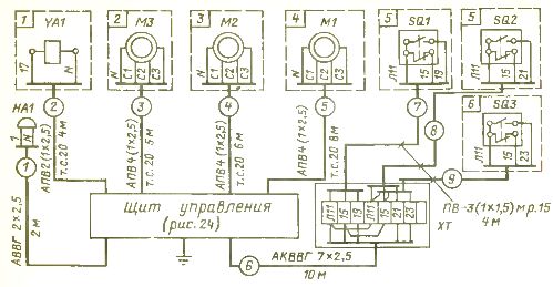
Rice. 5. Diagram of the external connection of the control panel and electrical equipment
In such a diagram, as in the previous example, the necessary process machines with their electrical equipment and the corresponding wiring are shown in accordance with the schematic diagram. It should be noted that it is permissible not to draw the wiring to the electric motors on the diagram, since they are available on the one-line diagram in fig. 2.
Layout of electrical equipment on the production line
The final drawing of the project is the layout of the electrical equipment (Fig. 6).The plan of the premises and simplified technological equipment is applied to it, the designed electrical equipment is placed, and in the symbols near which the reference designations are placed according to the previous project drawings, the wiring routes are shown and their conditional numbers are indicated according to the connection diagram and the one-line diagram.
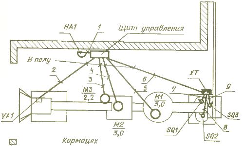
Rice. 6. Location of electrical equipment
This and the previous drawings are indispensable for the practical implementation of the project on site.