Crusher connection diagram
 Crushers of different designs are used to crush fodder grains and roughage. The working principle and circuit diagram of the control of the DB type sieveless sieve are shown in Figure 1.
Grinding grain using the auger 8 (Fig. 1) is loaded into the hopper 9, the level of which is automatically maintained based on information from two sensors. The supply of grain for grinding is regulated by a damper 10. In this case, the product of crushing is transported by air flow through the supply line to the filter 6.
Sufficiently crushed grain that has passed through the screen separator 4 is a finished product, which is discharged from the auger 2. The rest is returned to the crushing chamber, and the amount of this product is set by the operator using the regulating valve 5 (in the extreme right position, all material goes to discharge without fractionation). One part of the dusty air is returned to the shredding chamber, and the other part, passing through the filter 6, is discharged into the atmosphere.
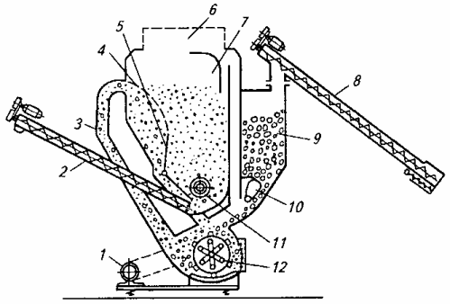
Rice. 1.Functional diagram of the DB-5 crusher: 1 — engine, 2, 8 — augers, 3 — air duct, 4 — separator, 5, 10 — shock absorbers, 6 — filter, 7 — chamber, 9 — grain hopper, 11 — agitator, 12 — rotor
The control circuit of the crusher (Fig. 2) provides sequential start of the unloading auger motors (M1) and then the crusher (M2), and to reduce the starting current, the crusher motor is connected in a «star» circuit, and then switched to a "delta" circuit. The filling auger is started by pressing the SB6 button with an empty crusher hopper.
The auger works until the SL1 contacts of the membrane sensor are closed at the upper level of the grain in the hopper. Magnetic starter KM4 and relay KV are de-energized when bypassed by contact SL1. The auger also restarts automatically after emptying the hopper and opening the contacts of the sensors of the upper levels SL1 and lower SL2.
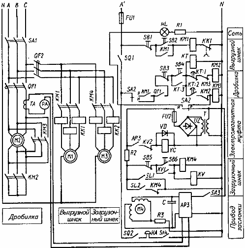
Rice. 2. Electrical diagram of the crusher
The capacity of the crusher is automatically regulated by means of a regulating valve moved by the M4 actuator under the command of the automatic load regulator (ARZ).
In the event of a significant overload of the motor and interruption of the power supply, the electromagnetic clutch YC, which connects the shock absorber to the IM, is disconnected from the contact ARZ, the shock absorber falls under its own weight and the supply of grain to the crushing chamber stops.
Full opening of the damper, indicating a reduction in crusher load, is signaled by the HA horn when limit switch SQ2 is closed.
Choppers, knives or hammers are used to chop hay and straw.The raw material to be crushed is fed into the feed hopper, which, as it rotates, throws it under the hammers of the rotor of the crushing chamber. The crushed mass is carried out of the chamber by the air flow generated by the rotary hammers.
The control circuit ensures sequential starting of the engines of the crusher and then (after 20 s) the hopper. In this case, the crusher is started by switching the motor from the "star" circuit to the "delta" circuit.
In the event of an overload on the crusher motor, the electromagnetic clutch is briefly disengaged and the feed to the crusher is interrupted. After reducing the load on the crusher, the power is resumed. If the motor overload lasts more than 20 s, the hopper drive motor is switched off.