Electrical diagram of the irrigation pumping station
 Irrigation pumping stations are used to fill reservoirs, raise water to the command marks of irrigated fields, divert irrigation discharge and pump groundwater, and during drainage - to pump sewage from channels and collectors, as well as to lower groundwater level.
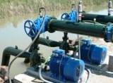
Pumping stations during land reclamation are characterized by high flow rates (up to hundreds of thousands of cubic meters per second) and high power (up to thousands of kilowatts). Asynchronous squirrel-cage motors are usually used for them.
Schemes of automation of pumping stations provide starting and stopping of electric motors, filling of pumps, control of shut-off valves, protection of pipelines under pressure from hydraulic shocks, protection of equipment in case of emergency, signaling of normal and abnormal modes of operation of equipment, monitoring and measurement of flow rate, pressure, water levels, etc. NS.
The pumping stations in the reclamation are equipped with special storage tanks and vacuum pumps for pre-filling the main pump with water.In their absence, the pumps are placed in buried chambers below the level of the tank, and the elbow of the suction pipe is located above the level of the pump.
To facilitate the start of the electric motor, electrified valves are installed on the pressure pipelines. The pump is started with a closed valve, after which the moment of water resistance is minimal. The valve opens automatically after the unit accelerates and establishes the set pressure, and also closes automatically when the electric pump is turned off.
As an example, let's consider the automation of an irrigation pumping station with pre-charging the pump with water and with control according to the water level in the suction structure (Fig. 1).
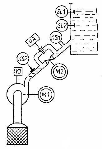
Rice. 1. Technological diagram of an irrigation pumping station
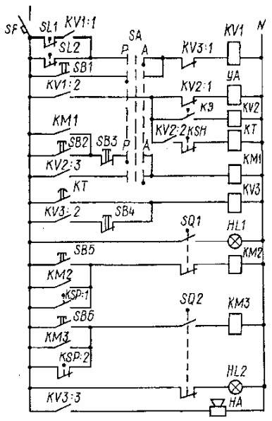
Rice. 2. Electrical schematic diagram of an irrigation pumping station (the power section with motors is not shown in the diagram).
In the manual control mode, the SA switch is placed in the P position and the operation of the equipment is controlled using the buttons SB1 — SB6.
In automatic mode, the switch SA is placed in position A, after which the circuit operates according to the timing diagram (Fig. 3).
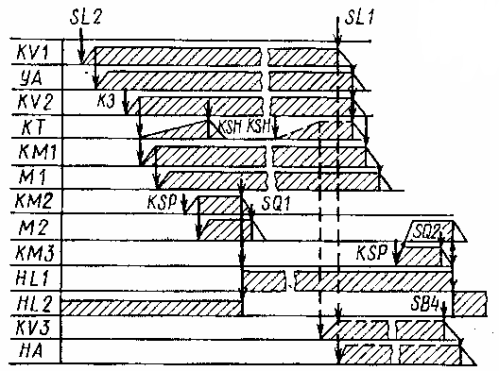
Rice. 3. Timing diagram
When the level in the water intake structure drops to the minimum permissible value, the contacts SL2 of the level sensor are closed and the relay KV1 is activated, which turns on the solenoid valve UA installed on the pump filling pipe. The pump is filled with water through this valve and the air in the pump is released through the short circuit relay.At the end of filling the pump with water, the short-circuit relay activates and turns on the relay KV, which in turn causes the magnetic starter KM1 and the time relay KT to turn on.
The magnetic starter starts the pump motor M1. When the engine accelerates, pressure is created in the exhaust pipe, from which the pressure switch KSP is actuated, which turns on the magnetic starter KM2 and the motor M2 to open the valve of the exhaust pipe. When the valve is fully open, the motor M2 is turned off by the limit switch SQ1 and the warning lamp HL1 lights up... At the same time, the contacts of the limit switch SQ2 are switched and the lamp HL2 goes out. Jet relay KSЗ reacting to the movement of water in the pipeline, it opens its contacts in the relay circuit for time KT and turns it off.
The pump is turned off by the SL1 sensor at the upper water level in the water pumping structure. Its contacts open the current circuits of the relay KV1, which turns off the electromagnet YA, the relay KV2, and then the magnetic starter KM1 and the motor M1 pump. The water pressure in the pressure line is reduced to the static pressure of the water column on the tank side. At this pressure, the contacts of the pressure switch KSP return to their original position, and the magnetic starter KMZ turns on the motor M2, which closes the valve.
When the valve is fully closed, the contacts of the limit switches SQ1 and SQ2 take their initial position, the contacts SQ2 turn off the motor M2. Automatic restart will occur when the water level drops before the SL2 contacts close.
Time relay KT is designed for emergency shutdown of the pump.If, for example, during start-up, water does not enter the suction structure, then the contacts of the KSH relay remain closed, the time relay turns on the XA alarm.
Relay KV1 turns off relay KV2 and the magnetic starter KM1, which stops the electric pump M1. The alarm relay is energized until the operator presses the SB4 release button. At the same time, the solenoid valve is disabled YA.
The same sequence of actions of the circuit to turn off the pump will be in the event of an accidental interruption of the water supply (dotted lines in Figure 3).