Varieties of relay circuits
Relay systems occupy a prominent place among the many automatic control devices. Their characteristic feature is a sharp change in the controlled (output) value when the input value changes. In other words, each element of the relay system can assume only two states: «on» or «off». The most typical and common are relay circuits consisting of contact electromagnetic elements (relays).
By the nature of work, relay systems are divided into single-cycle and multi-cycle.
In single-loop systems, the state of the drives is uniquely determined by the state of the receiving elements at any time. There is no clear sequence in their actions and therefore no need for intermediate elements. In other words, in a single-loop system, a certain combination of input signals (arguments) corresponds to a certain value of the output quantity (function). When describing the schemes of such systems, the concepts «before», «after», «bye», etc., which characterize the sequence of entering arguments, cannot be used.
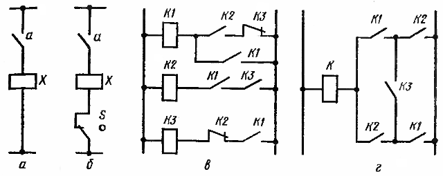
Rice. 1.Varieties of relay circuits: a — single-cycle, b — multi-cycle, c — type P, d — type H.
For example, in the single circuit shown in Figure 1, a, the action of the actuator X is uniquely dependent on the action of the receiving element — the closing contact a. There are no intermediate elements here.
In multi-cycle systems, a certain sequence is provided in the work of the receiving and executive elements, for the implementation of which the presence of intermediate elements is necessary. Therefore, several functions can match the arguments of the same combination, but according to data at different points in time.
So, in the circuit of Figure 1, b, the action of the actuator X is determined not only by the action of the receiving element - the closing contact a, but also by the intermediate element S.
An image of a diagram of a relay system, showing the number and composition of structural elements, as well as the configuration of connections between elements, is called a relay circuit structure. The part of a relay circuit containing only contacts is called a contact circuit.
Most often, the structure of relay circuits is depicted graphically in the form of symbols of elements and their connections. Each graphical element of the circuit receives a letter designation.
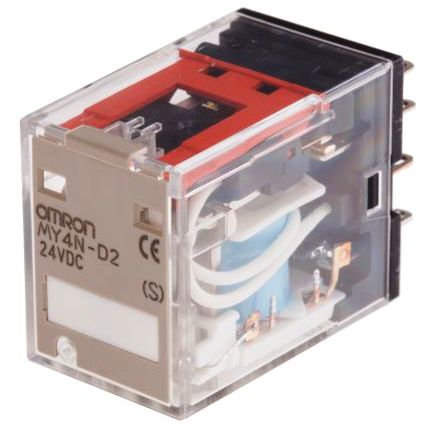
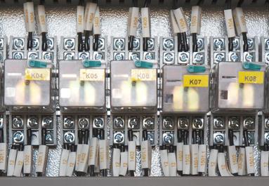
According to GOST, the coils of contacts, magnetic starters, relays are designated by the letter K. If there are several elements in the circuit, then a number corresponding to the serial number of the element on the diagram is added to the letter designation. You can use a two-letter designation: for example, the coils of a contactor, magnetic starter are designated as KM, time relay KT, voltage relay KV, current relay KA, etc.The contacts of the elements have the same designations as the coils. For example, K4 is the fourth relay and all contacts of this relay will have the same designation.
According to the type of connections, there are parallel-series circuits (type P) and with bridge connections (type H). In P-type circuits (Fig. 1, c), the contacts and coils of different elements are connected in series with each other, and individual circuits in parallel. In H-type circuits (Fig. 1, d), the presence of bridge elements (short-circuit element) leads to simultaneous series and parallel connections in different circuits. Bridge circuits have significantly fewer contacts than P-type circuits.
When studying relay automation systems, they mainly solve two problems:
-
the first is reduced to the analysis of relay circuits, that is, to the determination of the operating conditions of each relay and the sequence of their action,
-
the second — to the synthesis of schemes, that is, to finding the structure of the circuit according to the given conditions of its operation.
Analysis and synthesis make it possible to obtain an electrical diagram of the system with the minimum possible number of relays and contacts. When studying the stationary states of individual elements of relay automation systems, without taking into account their behavior over time, a special mathematical apparatus is widely used - the so-called algebra of logic.