DC Motor Control Methods in ACS
The control of a DC motor in ACS implies either changing the speed of rotation in proportion to a certain control signal, or maintaining this speed unchanged under the influence of external destabilizing factors.
There are 4 main control methods that apply the above principles:
-
rheostat-contactor control;
-
control by the «generator-motor» (G-D) system;
-
management according to the «controlled rectifier-D» (UV-D) system;
-
impulse control.
A detailed study of these methods is the subject of TAU and the Basics of Electric Drive course. We will consider only the main provisions that are directly related to electromechanics.
Rheostat-contactor control
Three schemes are commonly used:
-
when adjusting the speed n from 0 to nnom, the rheostat is included in the armature circuit (armature control);
-
if it is necessary to obtain n> nnom, the rheostat is included in the OF circuit (pole control);
-
to regulate the speed n <nnom and n> nnom, rheostats are included both in the armature circuit and in the OF circuit.
The above schemes are used for manual control.Step switching is used for automatic control. Rpa and Rrv using contactors (relays, electronic switches).
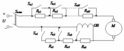
If precise and smooth speed control is required, the number of switching resistors and switching elements must be large, which increases system size, increases cost and reduces reliability.
Management of the G-D System
Speed regulation from 0 to according to the diagram in fig. produced by adjusting Rv (Uchange from 0 to nnom). To obtain a motor speed greater than nnom — by changing Rvd (reducing the current of the OB of the motor reduces its main flux Ф, which leads to an increase in the speed n).
Switch S1 is designed to reverse the motor (change the direction of rotation of its rotor).
Since the control of D is accomplished by adjusting the relatively small excitation currents D and D, it is easily adapted to ACS tasks.

The disadvantage of such a scheme is the large size of the system, weight, low efficiency, since there is a three-fold conversion of energy conversion (electrical to mechanical and vice versa, and at each stage there are energy losses).
Controlled Rectifier - Motor System
The "controlled rectifier - motor" system (see the figure) is similar to the previous one, but instead of an electrical machine source of regulated voltage, consisting of, for example, a three-phase AC motor and G = T controlled, for example, a three-phase thyristor electronic rectifier is also used.
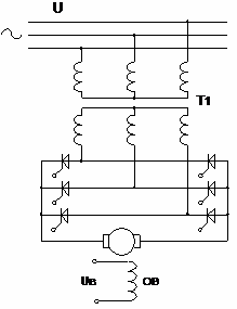
The control signals are generated by a separate control unit and provide the necessary opening angle of the thyristors, proportional to the control signal Uy.
The advantages of such a system are high efficiency, small size and weight.
The disadvantage compared to the previous circuit (G-D) is the deterioration of the switching conditions D due to the armature current ripple, especially when fed from a single-phase network.
Impulse control
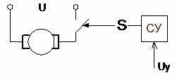
Voltage pulses are fed to the motor using a pulse chopper modulated (PWM, VIM) in accordance with the control voltage.
Thus, the change in armature rotation speed is achieved not by changing the control voltage, but by changing the time during which the rated voltage is supplied to the motor. It is obvious that engine operation consists of alternating periods of acceleration and deceleration (see figure).
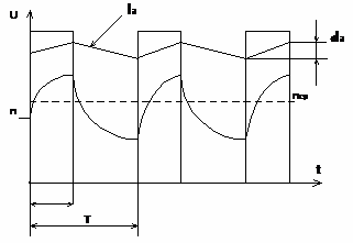
If these periods are small compared to the total acceleration and stop time of the armature, then the speed n does not have time to reach the stationary values nnom during acceleration or n = 0 during deceleration until the end of each period, and a certain average is set navigation speed, the value of which is determined by the relative duration of activation.
Therefore, the ACS requires a control circuit whose purpose is to convert a constant or variable control signal into a sequence of control pulses with a relative on-time that is a given function of the magnitude of that signal. Power semiconductor devices are used as switching elements — field and bipolar transistors, thyristors.