Rules and schemes for connecting PE protective conductors and equipotential bonding
In all buildings, the lines of the group network laid from group, floor and apartment shields to common lighting fixtures, plug sockets and stationary electrical receivers must be three-wire (phase — L, neutral working — N and neutral protective — PE wires).
It is not allowed to combine neutral working and neutral protective conductors from different group lines.
Working and neutral protective conductors cannot be connected under a common terminal. The selection of the cross-section of the wires must be carried out according to the requirements relevant chapters of PUE.
Single-phase two- and three-wire lines, as well as three-phase four- and five-wire lines when supplying single-phase loads must have a cross-section with zero working N wires equal to the cross-section of phase wires.
Three-phase four- and five-wire lines when supplying three-phase symmetrical loads must have a cross-section with zero working N conductors equal to the cross-section of the phase conductors, if the phase conductors have a cross-section up to 16 mm2 for copper and 25 mm2 for aluminum, and for large cross-sections-at least 50% of the phase conductors of the cross-section, but not less than 16 mm2 for copper and 25 mm2 for aluminum.
The cross-section of the PEN wires must be at least the cross-section of N wires and at least 10 mm2 for copper and 16 mm2 for aluminum, regardless of the cross-section of the phase wires.
The cross section of the PE conductors must be equal to the cross section of the phase conductors with a cross section of the latter up to 16 mm2, 16 mm2 with a cross section of phase conductors from 16 to 35 mm2 and 50% of the cross section of phase conductors with large cross sections . The cross-section of PE conductors that are not part of the cable must be at least 2.5 mm2 — in the presence of mechanical protection and 4 mm2 — in its absence.
Connection diagrams of PE protective conductors
The combined neutral and working wire PEN is divided into a neutral protective PE and a neutral working N wire in the input device.
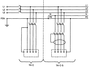 Implementation of the TN-C-S earthing system
The letter designations used in the figures have the following meanings.
The first letter is the nature of the grounding of the power supply: T — direct connection of one point of the current-carrying parts of the power source to the ground; N — direct connection of exposed conductive parts to the power supply ground point (usually the neutral is grounded in AC systems).
The following letters define the device of the zero work and zero protection wires: S — the functions of zero protection (PE) and zero work (N) are provided by separate wires; C — the functions of the zero protective and zero working conductor are combined in one conductor (PEN -conductor).
Working and neutral protective conductors cannot be connected under a common terminal. The meaning of this requirement is the need to ensure electrical safety conditions, preserving the connection of the protective conductor with grounding in case of destruction (burning) of the contact clamp.
Examples of connecting PE and N wires to PEN in floor or apartment panels
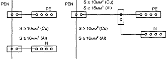
Examples of connecting PE and N wires to PEN
Rules for implementing the equipotential bonding system
In order to ensure electrical safety conditions in a certain electrical installation, the potential equalization system is important. The rules for applying the equipotential bonding system are defined by the standard IEC 364-4-41 and PUE (7th Edition)… These rules provide for the connection of all conductors to be grounded to a common bus.
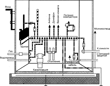 An example of the implementation of the equipotential bonding system
This solution avoids the flow of various unpredictable circulating currents in the grounding system, causing a potential difference in individual elements of the electrical installation.
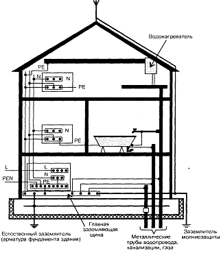 An example of the implementation of the potential equalization system in the electrical installations of a residential building Recently, with the increase in the equipment of modern residential buildings and industrial buildings with various electrical appliances and the constant development of their electrical installations, the phenomena of accelerated corrosion of pipelines of water supply and heating systems. In a short time — from six months to two years — point fistulas are formed on pipes from underground and aerial laying, which rapidly increase in size. Accelerated corrosion of pipes (pitting) in 98% of cases is caused by the flow of stray currents through them. The use of an RCD in combination with a properly implemented potential equalization system allows to limit and even exclude the flow of leakage currents, stray currents through the conductive elements of the building structure, including pipelines.