Principles of automatic start and stop control of electric motors
The article deals with relay-contactor schemes for automation of start, reverse and stop of induction motors with a phase rotor and DC motors.
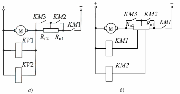
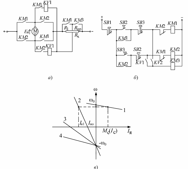
Consider the schemes for turning on the starting resistances and the contacts of the contactors KM3, KM4, KM5 that control them, when starting wound rotor induction motor (AD with f. R.) And Independently excited DC motor DPT NV (Fig. 1). These schemes provide for dynamic braking (Fig. 1, a) and opposite braking (Fig. 1, b).
When starting a DPT NV or IM rheostat with a phase rotor, alternate closing (short circuit) of the stages of the starting rheostat R1, R2, R3 is carried out automatically using the contacts of the contactors KM3, KM4, KM5, which can be controlled by three ways:
-
by counting time intervals dt1, dt2, dt3 (Fig. 2), for which time relays are used (time management);
-
by monitoring the speed of the electric motor or EMF (speed control).Voltage relays or contactors directly connected via rheostats are used as EMF sensors;
-
the use of current sensors (current relays adjustable for a return current equal to Imin) giving a command pulse when the armature (rotor) current decreases during the starting process to the value of Imin (control of the current principle).
Consider the mechanical characteristics of a DC motor (DCM) (Fig. 1) (for an induction motor (IM), it is the same if you use the operating section of the mechanical characteristic) during starting and stopping, as well as the curves of speed, torque ( current) versus time.
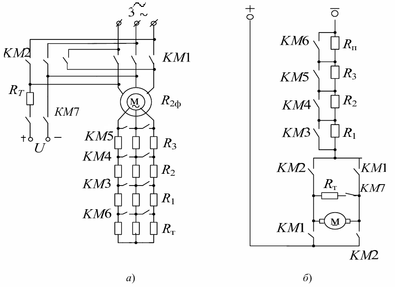
Rice. 1. Schemes for switching on the starting resistances of an induction motor with a phase rotor (a) and a DC motor with independent excitation (b)
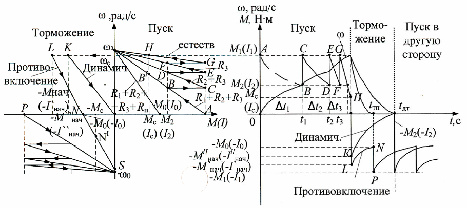
Rice. 2. Start and stop characteristics (a) and DPT dependencies (b)
Starting the electric motor (contacts KM1 are closed (Fig. 1)).
When voltage is applied, the current (torque) in the motor is equal to I1 (M1) (point A) and the motor accelerates with starting resistance (R1 + R2 + R3).
As the acceleration progresses, the current decreases and at current I2 (point B) R1 is short-circuited, the current increases to the value I1 (point C) and so on.
At point F, at current I2, the last stage of the starting rheostat is short-circuited and the electric motor reaches its natural characteristic (point G). Acceleration occurs to (point H) which corresponds to current Ic (load dependent). If R1 is not shorted at point B, then the motor will accelerate to point B' and have constant speed.
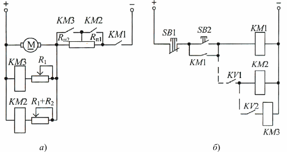
Dynamic braking (open KM1, closed KM7) until the electric motor goes to point K, which corresponds to the moment (current) and its value depends on the resistance Rtd.
Braking by opposition (KM1 open, KM2 close) while the electric motor goes to point L and starts decelerating very quickly with resistance (R1 + R2 + R3 + Rtp).
The slope of this characteristic, and hence the value, is the same (parallel) as the initial characteristic with the resistance (R1 + R2 + R3 + Rtp).
At point N, a short circuit Rtp is required, the electric motor goes to point P and accelerates in the opposite direction. If Rtp is not shorted at point N, then the motor will accelerate to point N' and run at that speed.
Automatic control schemes for starting DPT
Control as a function of time (Fig. 3) Most often, electromagnetic time relays are used as time relays in EP circuits. They are set to account for the preset time delays dt1, dt2,…. Each time relay must include a corresponding power contactor.
Rice. 3. Schematic of automatic start of DPT as a function of time
Control as a function of speed (most often used for dynamic braking and opposite braking) This principle of control automation involves the use of relays that directly or indirectly control the speed of the electric motor: for DC motors the armature emf is measured, for asynchronous and synchronous electric motors, the EMF or current frequency is measured.
The use of devices that directly measure speed (speed control relay (RCC) on a complex device) complicates the installation and control circuit.RKS is more often used for braking control to disconnect the electric motor from the grid at a speed close to zero. Indirect methods are more often used.
At constant magnetic flux, the armature emf of the DPT is directly proportional to the speed. Therefore, the voltage relay coil can be connected directly to the armature terminals. However, the armature terminal voltage Uy differs from Eya in the magnitude of the voltage drop across the armature winding.
In this case, two options are possible:
- the use of KV voltage relays, which can be adjusted to different actuation voltages (Fig. 4, a);
- using KM contactors connected through starting resistors (Fig. 4, b). The closing contacts of the KV1, KV2 relay supply voltage to the coils of the power contactors KM2, KM3.
Rice. 4. DPT connection power circuits using voltage relays (a) and contactors (b) as DCS
Rice. 5. Electrical circuit (a) and control circuit (b) DPT with speed-dependent start-up automation. Dashed lines show the circuit when voltage relays KV1, KV2 are used to measure the voltage.
Control in the current function. This control principle is implemented using undercurrent relays, which turn on the power contactors when the current reaches the value I1 (Fig. 6, b). It is most often used to start up to increased speed with a weakening of the magnetic flux.
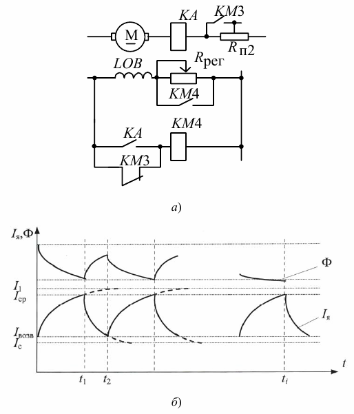
Rice. 6. Connection diagram (a) and dependence of Ф, Ia = f (t) (b) when starting a DC motor depending on the current
When inrush current (Rp2 is shorted) the KA relay is energized and power is applied to coil KM4 through the KA contact.When the armature current decreases to the reverse current, the contactor KM4 closes and the magnetic flux decreases (Rreg is introduced into the LOB field winding circuit). In this case, the armature current begins to increase (the rate of change of the armature current is higher than the rate of change of the magnetic flux).
When Iya = Iav is reached at point t1, relays KA and KM4 are activated and Rreg is manipulated. The process of increasing the flux and decreasing Ia will begin by time t2 when the spacecraft and KM4 turn off. With all these commutations, M> Ms and the electric motor will accelerate. The starting process ends when the magnitude of the magnetic flux approaches the set value determined by the introduction of the resistance Rreg in the circuit of the excitation coil and when, at the next disconnection of KA, KM4, the armature current does not reach Iav (point ti). This control principle is called vibration.
DPT brake control automation
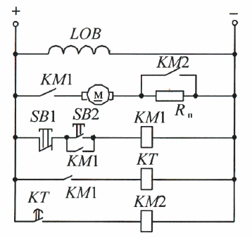
In this case, the same principles apply as for startup automation. The purpose of these circuits is to disconnect the electric motor from the network at a speed equal to or close to zero. It is most easily solved with dynamic braking, using the principles of time or speed (Fig. 7).
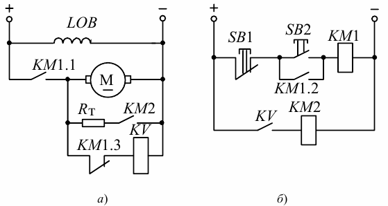
Rice. 7. Electrical circuit (a) and control circuit (b) dynamic braking
When starting, we press SB2 and the voltage is supplied to the coil KM1, while: the button SB2 (KM1.2) is manipulated, the voltage is applied to the armature of the motor (KM1.1), the supply circuit KV (KM1.3 ) opens.
When stopping, we press SB1 while the armature is disconnected from the network, KM1.3 closes and the KV relay is activated (since at the moment of shutdown it is approximately equal to Uc and decreases with a decrease in speed). Voltage is supplied to coil KM2 and RT is connected to the armature of the motor. When the angular velocity is close to zero, the armature of the KV relay disappears, KM2 is de-energized and RT is turned off. The KV relay in this circuit must have the lowest possible feedback factor, because only then is it possible to achieve braking to the minimum speed.
When the motor is reversed, counter-switching braking is used and the control circuit's job is to introduce an additional resistance stage when the reverse command is given and bypass it when the motor speed is close to zero. Most often, for these purposes, control is used as a function of speed (Fig. 8).
Rice. 8. Electrical circuit (a), control circuit (b) and braking characteristics (c) of reverse DPT braking
Consider a circuit without a startup automation block. Allow the electric motor to run «forward» naturally (including KM1, acceleration is not taken into account).
Pressing the SB3 button turns off KM1 and turns on KM2. The polarity of the voltage applied to the armature is reversed. Contacts KM1 and KM3 are open, impedance is introduced into the armature circuit. An inrush current appears and the motor moves to characteristic 2, according to which braking takes place. At a speed close to zero, relay KV1 and contactor KM3 should turn on. The Rpr stage is manipulated and the acceleration starts in the opposite direction according to characteristic 3.
Characteristics of Induction Motor (IM) Control Circuits
1. Induction Speed Control (RKS) relays are often used to control braking (especially reverse).
2. For IM with a wound rotor, KV voltage relays are used, which are triggered by different values of rotor EMF (Fig. 9). These relays are switched on through a rectifier to exclude the influence of the frequency of the rotor current on the inductive resistance of the coils of the relay itself (with a change in XL changes and Iav, Uav), reducing the coefficient of return and increasing the reliability of operation.
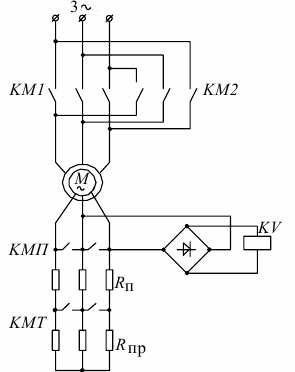
Rice. 9. Reverse blood pressure arrest scheme
Principle of operation: at a high angular speed of the rotor of the electric motor, the EMF induced in its windings is small, since E2s = E2k · s, and the slip s is negligible (3–10%). The KV relay voltage is not sufficient to pull its armature. In reverse (KM1 opens and KM2 closes), the direction of rotation of the magnetic field in the stator is reversed. The KV relay operates, opens the supply circuit of the KMP and KMT contactors, and the starting Rп and braking Rп resistances are introduced into the rotor circuit. At a speed close to zero, the KV relay turns off, the KMT closes, and the motor accelerates in the opposite direction.