How to protect your home network during a thunderstorm
Network lightning protection
 Builders of local and home networks are certainly familiar with the feeling when a network, launched after a long work, works ... for a day or two, and then they have to climb into the attic and replace the burnt hub. Thunderstorms are usually the scourge of networks. In a large network, no thunderstorm passes without loss.
Worn out with burnt hubs, a person, of course, comes to the question: is it really impossible to do something? Of course you can—and you should! It is necessary, firstly, to correctly plan and execute the wiring, and secondly, to use lightning protection devices (also known as mains fuses).
Such devices can be purchased. Of those available on the market, two classes can be distinguished: "branded" and "self-made". The brand class is represented mainly by APC products — these are different models under the general name ProtectNet. These devices are distinguished by a rather high price — and rather low reliability (see why below). As for self-made devices manufactured by several LLCs and PBOULs, they are all about the same.Their inherent reliability is higher than that of APC devices, but the protective properties are about the same.
You can also make such devices yourself. How — read in this article.
First, some reasoning. What is the diagnosis when the hub burns out? Electrical failure. How is "redundant" electricity can it enter the hub? Via BNC, UTP and power connectors. The mechanism for the formation of this electricity? The build-up of static charges on an overhead line induced EMF from high voltage lines causes an EMF from a lightning discharge. Protection method? Dumping excess electricity to the ground.
I note right away that none of the devices discussed in this article are able to protect against a direct lightning strike. However, I am not yet aware of any cases of direct lightning strikes on LAN wires.
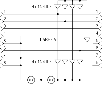
You can make protection for a twisted pair according to the following scheme:
 Rice. 1.
The line is connected to the connector on the left, the hub is connected to the one on the right. Dischargers — gas, for voltage 300V (I used CSG -G301N22). The distance from the device to the hub is as small as possible.
The principle of operation is clear from the diagram. A polyphase diode bridge with a protection diode in the diagonal acts as a potential equalizer, limiting the maximum potential difference of any two wires to a level of about 10 V. A potential above 300 V with respect to ground is extinguished by the arrester.
Almost all devices currently on the market are made according to a similar scheme, but there are also important differences. APC uses so-called semiconductor pseudo-spark gaps instead of gas dischargers. These elements are extremely cheap, but their reliability does not stand up to criticism.They are able to protect against static, but burn immediately from the induced electricity in a nearby lightning strike. The lightning protection built into the APC UPS uses a different solution — air spark. Such a scheme, on the contrary, works only at a very high induced voltage — when, as a rule, there is nothing to spare.
Craftsmen at various LLCs noticed this feature and solved the problem in their own way: in almost all devices manufactured in Russia, arresters are simply absent. Instead, a «hard» (with various variants) earth connection is used. The advantages of this solution are obvious, the disadvantages — alas, too. With a sufficiently large potential difference between the grounding points from different ends of the line, the equalizing current begins to flow through the cables and devices, which can reach huge values and burn everything on the way you are
The circuit parameters are shown in Fig. can be improved:
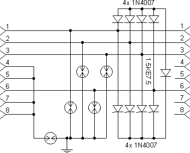 Fig. 2.
Here, each wire is connected to ground via a separate arrester, which achieves a much faster protection response (the arrester trips 3 orders of magnitude faster than the 1N4007 diode and an order of magnitude faster than the protection diode). The disadvantage of this scheme is the large number of relatively expensive (2-3 USD) arresters. The circuit can (but is not desirable) be simplified by using only one limiter per pair (e.g. from pins 1 and 3 only). In any case, it is necessary to use specialized restraints.The use of neon bulbs or fluorescent lamp starters (as some recommend) instead of arresters is possible, but it should be noted that they have a much slower response rate, higher breakdown resistance and lower allowable energy of demolition.
An important point that almost all manufacturers of netprotects forget about: protection of the power hub. For a conventional 7.5 V DC powered hub, the protection can be done as follows:
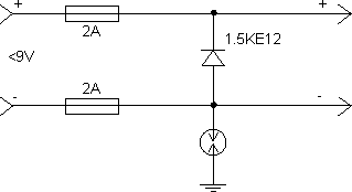
Fig. 3.
As with twisted pair protection, this device should be located as close to the hub as possible.
For hubs with a built-in power unit, no additional protection is required. The only condition is that there is a reliable protective ground connected to the middle pin of the plug.
If a conductive run is used when extending an overhead line (usually a field worker), it must be grounded. Attention - you need to ground the traverse only from one end (here I have to argue with the authors of other well-known articles on the Internet on this topic).
Unfortunately, even in new buildings, when conducting an electrical network, far from all and not always are guided by the requirements of the Rules for the arrangement of electrical installations. Let's face it, nobody. I saw a house (a modern brick 9-story building, put into operation, by the way, after the appearance 7th edition of PUE), in which each input is fed by an aluminum wire with a cross section of 2.5 sq. mm. !!! Accordingly, if you "ground" the traverse in such a house and in a house with normal grounding, the whole house will be powered through your traverse! 🙂
In the same way, you can perform linear protection based on coaxial cable.The most optimal solution: The equalizing bridge is connected to the braid and the middle wire. In such a scheme, you will need 2 restraints - from the braid and the core to the ground. I do not recommend grounding the coaxial cable braid when creating an overhead line between buildings.
In conclusion, a few words about the effectiveness and necessity of the described devices. During the test check, the devices were connected to the UTP overhead line about 60 m long. When the line is connected (the other end is free!), a bright glow is observed in the dischargers. After the final installation of the line, the arresters "wink" at an interval of 20-50 seconds, i.e. not the longest line in calm weather gets 300 V static potential in less than a minute!
Powering the hub
It's no secret that in places where hubs are installed, there is not always a 220V outlet. Therefore, you either have to begrudgingly tinker with the network topology to put the hubs in more appropriate locations, or consider powering from afar.
Faced with such a problem, «wow-master» sometimes solve it simply - supply 220V, using free pairs in the cable (UTP) or using RG-58 coaxial. Of course, such a "solution" cannot be considered acceptable in any way, since in this case there can be no question of any electrical and fire safety. Even if the fire happened for a completely different reason, the author of such a publication is guaranteed to be the first candidate for the culprit.
It seems more competent to conduct a 220V network using a suitable cable (copper core, double insulated, at least 0.75 sq.m.).With a quality installation, this can be considered a normal option; however, when locating the hub in a fire-failed area—for example, in the attic of a log house—you'll need to pay attention to outlet placement and insulation. In addition, local electricians look very askance at any "alien" 220V lines.
In some cases (for example, a hub or a switch with a built-in power supply), a 220V network cannot be avoided. In most variants, however, hubs with an external power supply are installed, the output voltage of which is usually 7.5V. Such a hub can be powered by "low" voltage. Let's look at the possible options:
A typical hub requires 7.5V DC. The operating current of the hub is usually slightly less than 1A. A voltage of 7.5V is absolutely safe from the point of view of breaking the insulation of wires, but it will not be so easy to bring it "from afar". The fact is that cheap hubs are very important for size and especially for power supply purity, and over long distances voltage drop is inevitable, as well as the appearance of pickups.
The solution is to install a stabilizer at 7.5-8V directly near the hub until the mains voltage can be increased.
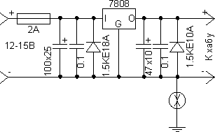
Figure 2.1.
The output voltage is selected equal to 13.2V (12-14V) based on its wide distribution (voltage in the car's on-board network). The range of commercially available power supplies for this voltage is very wide. Of course, several hubs can be powered from one power supply by extending the lines to them and equipping each of them with its own stabilizer according to the scheme in Figure 2.1.In this case, the operating current of the power supply should be calculated based on 2A per hub. If the number of hubs is more than 10, you can count 1.5A / hub. The stabilizer IC must be equipped with a heatsink.
The logical continuation of this scheme is the diagram in fig. 2.2.
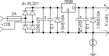
Figure 2.2.
Here, the stabilizer is supplemented with a rectifier, which allows the use of alternating voltage and saving the cost of the power supply by replacing it with a transformer. The operating current of the transformer should also be calculated based on 1.5 - 2A per hub (assuming 1A rated hubs are used). As a transformer, TN (incandescent filament) series devices with windings connected in series (or series-parallel) are suitable for obtaining a voltage of 12.6V.
Both considered schemes contain elements for protection against impulse noise in the power supply, against static, against overvoltage and polarity reversal.
Unused pairs in UTP can be used as a power line. The wires in them must be connected in parallel in pairs (blue + white, brown + white-brown). UTP Category 5 connected in this way can power up to 3 hubs. Such a connection will pass without problems at a line speed of 10 Mb / s; at 100Mb / s "unpacking" the cable is undesirable, although, as a rule, with careful installation, everything works without problems.
A typical topology in this case may look like this: the line entering the house is connected to a switch located near the 220V outlet. The transformer is powered from the same outlet. The UTP lines run from the switch (and transformer) to the access (floor) hubs, while only one UTP strand is needed for each hub.
It also becomes possible to create a long "range" consisting of hubs or switches, with a power connection in only one place.
When used as a main body according to FIG. 2.2. (with alternating current in the line) remote connection of hubs with built-in power supply is also possible. Such a hub is connected using one more transformer (eg TN series) included for «amplification».
Instructions for the device for lightning protection of buildings and facilities
