An example of drawing up a timing diagram and a block diagram of the operation of mechanisms
In the control schemes of the technological lines, the state of the output elements, i.e. actuators (electromagnetic relays, magnetic starters, solid-state relays, etc.), is determined not only by the combination of input or receiving elements (buttons, sensors, etc.), but also by the sequence of their change over time.
A verbal description of the designed technological process can be presented in the form of a schedule of changes in input and output signals, which is called a time diagram of the technological process.
An example of building a timing diagram will be made based on a grain pre-cleaning line diagram.
Description of circuit operation
Using the SA1 switch, the operating mode is selected: automatic — the main operating mode, manual — commissioning mode.
The commissioning mode consists of supplying power through the locking buttons SB4-SB6 to the coils of the magnetic starters of the linear mechanisms, bypassing all control logic. In this mode, the operator himself decides on the length of the line or some separate mechanism, the control of the filling of the hopper is carried out only visually.
As a rule, this mode of operation is used either in emergency modes of operation, when the control logic is broken and it is necessary to complete the technological process without losing the product on the line, or during commissioning, when after repair of some mechanism on the line, it is necessary to start only it, not all linear mechanisms.
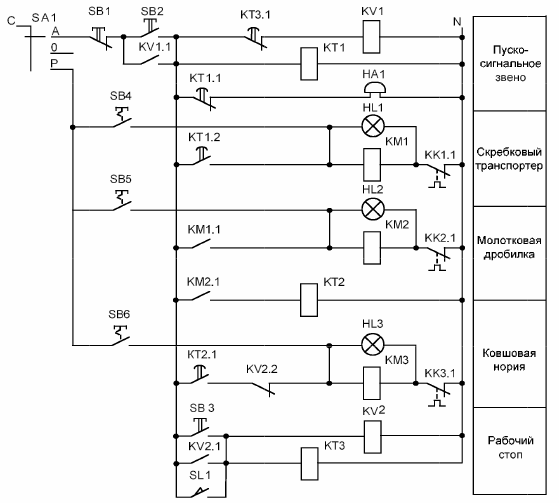
Rice. 1. Relay-contact control circuit of the grain pre-cleaning line
After the operating mode switch, a start-up signaling block is included in the control circuit, which allows, with a time delay, to simultaneously turn off the bell and turn on the scraper conveyor. When composing relay-contact circuits, the sequence of turning on or off the mechanisms is carried out by means of the closing contacts of the magnetic starters.
So in our case, if there is energy on the coil of the magnetic starter KM1 (scraper conveyor), respectively, through the contact KM1.1, the power will also be on the coil of the magnetic starter KM2 (hammer) .
At the same time, it is impractical to start all the mechanisms of the line, because during operation such an operation mode may occur when the electric drives of the two mechanisms of the line have not yet reached their nominal operation mode, and the product is delivered to them through the head mechanism, resulting in an emergency stop of the line. Therefore, in the control circuit, power is supplied to the coil of the magnetic starter KM3 of the head mechanism with a time delay realized by the time relay KT2.
The linear mechanisms are engaged, the work is in progress. Sometimes during operation there comes a time when the hopper is not yet full and the line must be turned off. In this case, a "work stop" block is used in the control scheme, which makes it possible to turn off all mechanisms of the line in the correct sequence (in the direction of the movement of the product along the line).
So, when the SB3 button is pressed, the intermediate relay KV2 turns on, the opening contact of which KV2.2 breaks the circuit with the coil KM3, the line head mechanism is turned off. At the same time, the time relay KT3 prepares a report on the operation time of the line for cleaning the mechanisms from the product.
After a certain time, the contact of the time relay KT3.1 breaks the circuit with the intermediate relay KV1, whose contact bypasses the start button. This causes the entire control circuit to stop and, as a result, the linear mechanisms to stop. A similar algorithm for the operation of the control circuit when triggering the level sensor in the SL1 hopper.
The protection of linear electric motors from overload in the presented control scheme is carried out by means of interrupting contacts of thermal relays KK1.1 ... KK3.1, which are installed respectively in series in circuits with coils of magnetic starters KM1 ... KM3.
For visual control of the operation of the linear mechanisms in the control circuit there are indicator lamps HL1 ... HL3. In normal operation of the linear mechanisms, the indicator lamps will light up. In the event of an emergency shutdown, the power in the circuit with the magnetic starter disappears and the indicator lamp goes out accordingly.
According to the scheme of the electrical main automatic mode of operation, 3 buttons are needed for the grain pre-cleaning line: SB1 «Stop», SB2 «Start» and SB3 «Work stop», as well as a level sensor SL1. Thus we have 4 input elements. Also, buttons are accepted with self-return, i.e. without fixing the power-on state.
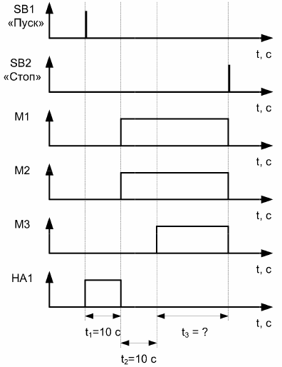
An example of building a time chart
Output items 4: bell HA1, scraper conveyor KM1, hammer crusher KM2 and bucket elevator KM3.
When the SB2 «Start» button is pressed, the first trigger link (bell HA1) should be activated for 10 seconds to warn the personnel that the process line is about to start.
After HA1's bell rings, ie. 10 seconds after pressing the "Start" button SB2 86, the scraper conveyor KM1 and the impact crusher KM2 are turned on (see Fig. 2).
The working time of the mechanisms is determined based on their productivity and production volume. The productivity of the scraper conveyor, hammer crusher and bucket elevator is 5 t / h, 3 t / h and 2 t / h respectively. The grain volume is determined based on of the volume of the hopper and a kilogram of grain per 1 m3.
The grain of different crops has a different shape, density and corresponding weight, therefore a cubic meter of each type of grain cannot weigh the same.
Let's take the volume of the bunker 5 m. The loaded grain is buckwheat, which weighs 560 - 660 kg. The initial state of the recycle bin is empty. Then the amount of grain in a full container: N = 580 x 5 = 2900 kg.
The bucket elevator has the lowest productivity of all mechanisms; he also supplies grain to the line. Its working time will be: Tm3 = 2000/2900 = 0.689 h = 41 min.
The working time of the remaining mechanisms will be more than 41 minutes and is determined based on the logic of the circuit.
After turning on the scraper conveyor KM1 and the impact crusher KM2, they must be given time to accelerate. The acceleration time for all mechanisms is taken — 10 seconds. Bucket lifter KM3 is started last (10 seconds after starting KM1 and KM2) so as not to create a product blockage on the hammer crusher KM2 and the scraper conveyor KM1. After 41 minutes, all the product needed to fill the hopper will pass through the KM3 bucket elevator.
The SL level sensor is installed in such a way that the hopper filling signal is received even before the product residues pass through the hammer crusher KM2 and the scraper conveyor KM1.
When the SL1 level sensor is actuated, the KM3 head mechanism is turned off (after 41 minutes and 20 seconds after pressing the SB2 «Start» button). With a time delay, KM1 and KM2 turn off simultaneously. This time delay can be assumed equal to 20 seconds.
The timing diagram for normal operation is shown in Figure 2.
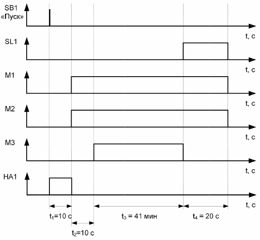
Rice. 2. Timing diagram for normal operation
In «Operation stop» mode, the operator can stop the process before triggering the level sensor SL1, therefore in this case it is impossible to determine the time of operation of the mechanisms. In «General stop» mode, all mechanisms are immediately deactivated.
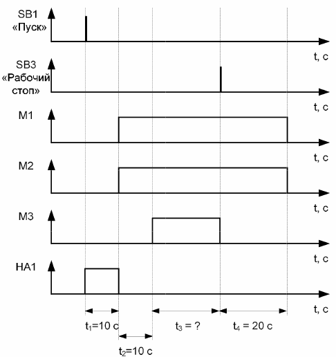
Rice. 3. Timing diagram for the «Operation stop» mode of operation
Rice. 4. Timing diagram for the «Total stop» mode
An example of building a block diagram of the operation of the mechanisms
The block diagram of the technological process must clearly show the algorithm of its work. For this, special designations of certain actions are used.
Figure 5 shows an example block diagram for a grain precleaning line. The presented block diagram shows all possible options for the functioning of the technological process. The "Accident" situation can occur at any time during the operation of the grain pre-cleaning line after pressing the "Start" button SB2.
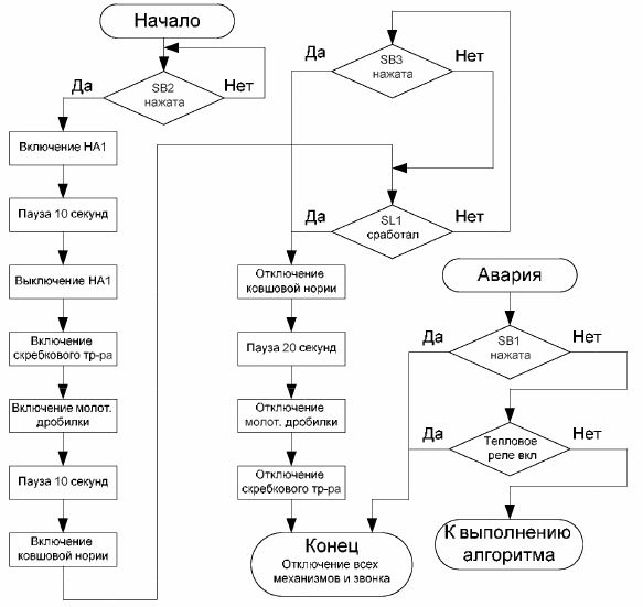
Rice. 5. Block diagram of the grain pre-cleaning line